
Electromagnetic orthopedic device and orthopedic method

An orthopedic and electromagnetic technology, applied in forming tools, manufacturing tools, metal processing equipment, etc., can solve the problems of poor flexibility, increased manufacturing costs, insufficient electromagnetic force, etc., to meet complex and accurate orthopedic requirements, reduce design and manufacturing costs, The effect of meeting the needs of forming

Active Publication Date: 2022-03-18
HUAZHONG UNIV OF SCI & TECH
View PDF5 Cites 0 Cited by
  • Summary
  • Abstract
  • Description
  • Claims
  • Application Information

AI Technical Summary

Problems solved by technology

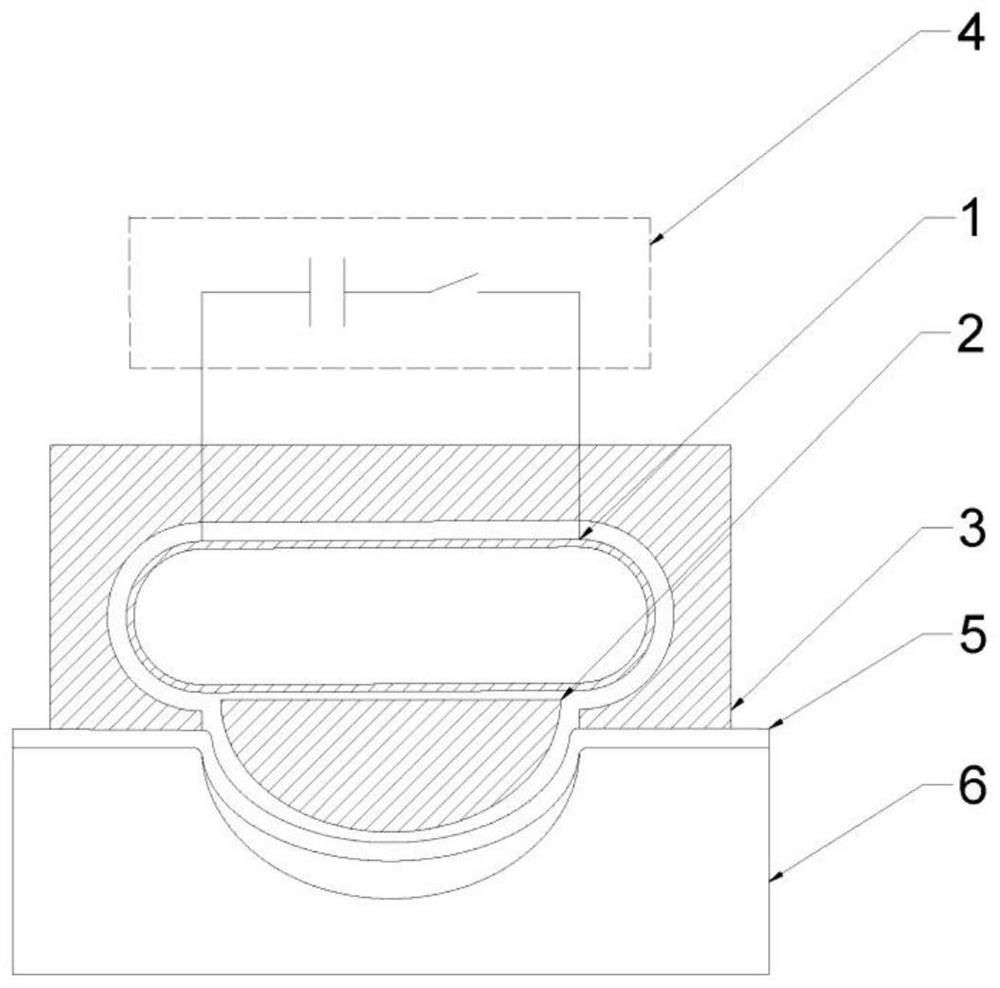
In the electromagnetic forming of the plate, there are the following common problems: (1) In the one-time forming method, the plate may have a certain error between the size of the plate and the mold size due to insufficient discharge energy or the rebound of the material, or it may be caused by the discharge Excessive energy leads to local wrinkling due to the collision between the plate and the mold; (2) In the multiple incremental forming method, the part of the plate has not yet been attached to the mold after the initial forming, and the distance between the local area of ​​the plate and the coil during subsequent forming If it is stretched, the magnetic field intensity generated during the forming process will be significantly reduced, resulting in insufficient electromagnetic force required for forming, which will affect the forming accuracy of the sheet; The required forming process (such as the forming of local complex features) is difficult
For the above problems, the method of using a special shape to drive the coil will increase the difficulty of coil design, resulting in increased manufacturing costs, poor flexibility, and a single application range of the coil.

Method used


Image

  • Electromagnetic orthopedic device and orthopedic method
  • Electromagnetic orthopedic device and orthopedic method
  • Electromagnetic orthopedic device and orthopedic method

Examples


Embodiment 1

[0069] Such as Figure 4 As shown, one embodiment of the present invention provides an electromagnetic orthopedic device and an orthopedic method based on the device for orthopedromes with a workpiece for insufficient forming precision caused by the plate material. The electromagnetic orthopedic device includes: a constant pressure drive coil 1, a magnetic field shaping device 2, a conductive passage 3, a power source 4, a workpiece 5, and a mold 6. Among them, the uniform pressure drive coil 1 is a uniform pressure coil of the single layer of the copper wire, the wire cross-section size is 2 mm × 4 mm, a total of 18 turns; the outer surface profile of the magnetic field plaster 2 is the same as the contour of the mold, the material is copper, magnetic field shaping machine 2 Mechanically connected between the conductive channel 3 to constrain its position; the contour of the conductive passage 3 is the same as the outer surface profile of the uniform pressure drive coil 1, the mat...

Embodiment 2

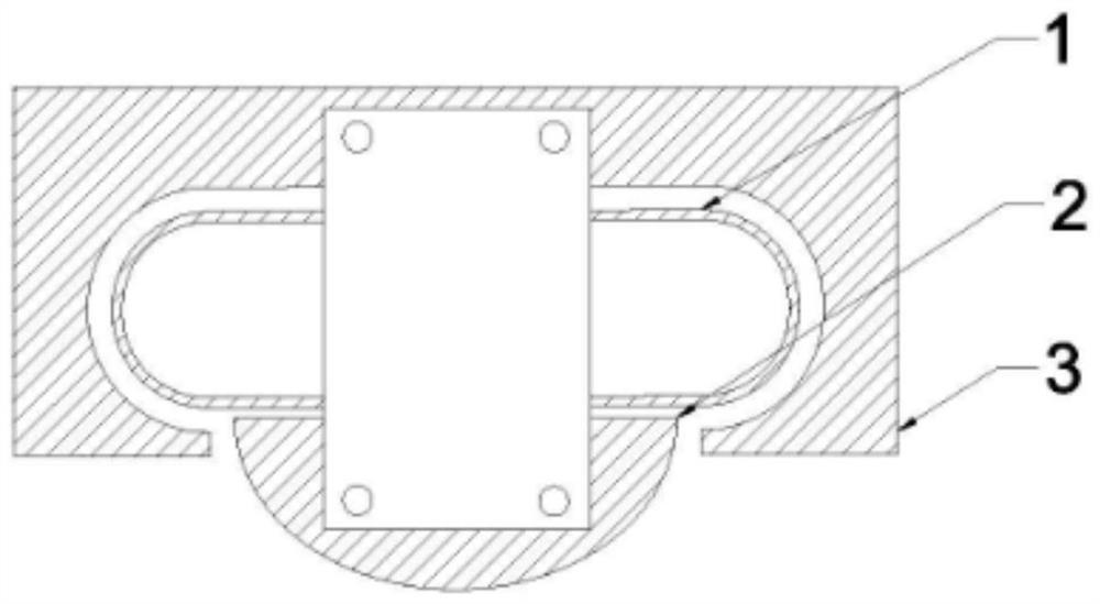
[0077] Such as Figure 5 As shown, one embodiment of the present invention provides an electromagnetic orthopedic device and an orthopedic method based on the device for multiple progressive forming of long straight plate members. The electromagnetic orthopedic device includes: a constant pressure drive coil 1, a magnetic field shaper 2, a conductive passage 3, a power supply 4, a workpiece 5, and a mold 6. Among them, the uniform pressure drive coil 1 is a uniform pressure coil of the single layer of the copper wire, the wire cross-section size is 2 mm × 4 mm, a total of 18 turns; the outer surface profile of the magnetic field plaster 2 is the same as the contour of the mold, the material is copper, magnetic field shaping machine 2 Mechanically connected between the conductive channel 3 to constrain its position; the contour of the conductive passage 3 is the same as the outer surface profile of the uniform pressure drive coil 1, the material is copper; the power supply 4 is a ca...

Embodiment 3

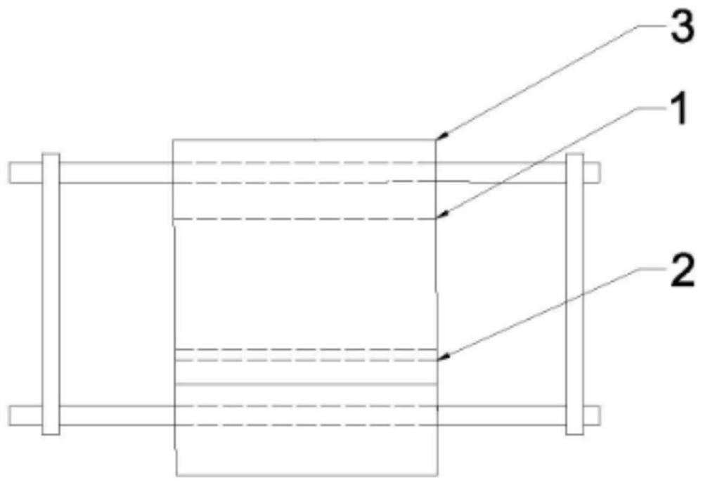
[0087] Such as Image 6As shown, one embodiment of the present invention provides an electromagnetic orthopedic device and an orthopedic method based on the device for local complex feature of the preformed workpiece. The electromagnetic orthopedic device includes: a constant pressure drive coil 1, a magnetic field shaper 2, a conductive passage 3, a power supply 4, a workpiece 5, and a mold 6. Among them, the uniform pressure drive coil 1 is a uniform pressure coil of the single layer of the copper wire, the wire cross section size is 2 mm × 4 mm, a total of 18 turns; the outer surface profile of the magnetic field plaster 2 is the same as the inner surface of the mold, the material is copper, magnetic field The planer 2 is mechanically connected to the conductive passage 3 to restrain its position; the contour of the conductive passage 3 is the same as the outer surface profile of the homogeneous pressure drive coil 1, the material is copper; the power supply 4 is a capacitive en...


PUM


Abstract

The invention discloses an electromagnetic orthopedic device and an orthopedic method, belonging to the technical field of metal forming manufacturing, comprising a uniform pressure drive coil, a magnetic field shaper, a conductive channel and a mold; the uniform pressure drive coil is arranged inside the conductive channel; the conductive channel and the The orthopedic workpiece forms a conductive circuit; the magnetic field shaper is arranged between the uniform pressure drive coil and the workpiece to be orthoped; the uniform pressure drive coil generates a pulsed magnetic field around it through pulse current discharge, and the pulsed magnetic field generates an induced eddy current on the surface of the magnetic field shaper; the magnetic field The shaper cooperates with the uniform pressure driving coil to generate an induced current in the conductive circuit, and the induced current generates a pulse electromagnetic force on the area to be shaped of the workpiece to be corrected; the area to be formed of the workpiece to be corrected is deformed to the mold under the action of the pulse electromagnetic force. The invention can flexibly and accurately control the orthopedic or multiple forming processes of the workpiece through the optimized design of the magnetic field shaper, effectively reducing the design difficulty and manufacturing cost of the forming device.

Description

Technical field [0001] The present invention belongs to the field of metal forming manufacturing, and more particularly to an electromagnetic orthopedic device and an orthopedic method. Background technique [0002] Lightweight alloy materials provide effective implementation of industrial production of automobiles, aerospace and other fields. Meanwhile Studies have shown that high-speed forming can effectively improve the formation performance of light alloy at normal temperature. Therefore, electromagnetic forming techniques have been widely used in the field of processing of light alloy materials such as aluminum alloys. [0003] In the electromagnetic forming technique of non-axisymmetric panels, the use of a homogeneous driving coil is a functional method. In the electromagnetic forming of the panel, there is a common problem: (1) In the primary forming method, the panel may cause a certain error of the panel size and the mold size due to the bulk of the discharge energy or ...

Claims


Application Information

Patent Timeline
Patent Type & Authority Patents(China)
IPC IPC(8): B21D26/14B21D1/00B21D37/10
CPCB21D26/14B21D1/00B21D37/10
Inventor 李亮张子轩赖智鹏郑宇李昌兴韩小涛曹全梁
Owner HUAZHONG UNIV OF SCI & TECH
Learn More