Electric valve

A technology of electric valves and valve ports, which is applied to valve devices, valve details, engine components, etc., and can solve problems such as inconstant volume, uncertain direction, harsh sound, etc.

Active Publication Date: 2015-06-03
SAGINOMIYA SEISAKUSHO INC
View PDF6 Cites 11 Cited by
  • Summary
  • Abstract
  • Description
  • Claims
  • Application Information

AI Technical Summary

Problems solved by technology

[0013] However, in the electric valve 800 described above, in the above-mentioned fixed-point control, when the movable stopper 863 rotates and the claw 865 touches the limit wire body 861, it will move in the direction opposite to the rotation due to its reaction. After springing back, such as Figure 12 As shown in (b), the cross-section of the claw portion 865 is formed in a circular shape, and the claw abutment surface 844a on which the claw portion 865 of the pin-shaped protrusion 844 abuts is formed to be parallel to the limit wire body portion 861. When 865 hits the limit line body 861, the direction of the force (indicated by an arrow in the figure) applied to the claw 865 is uncertain, so the amount of rebound due to the above-mentioned reaction is not constant. Therefore, there are the following problems: Uneven volume of the sound produced by being bounced back, resulting in a harsh sound

Method used


Image

  • Electric valve
  • Electric valve
  • Electric valve

Examples


no. 1 approach

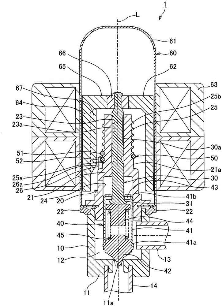
[0044] Below, refer to Figure 1 to Figure 7 An electric valve according to a first embodiment of the present invention will be described.

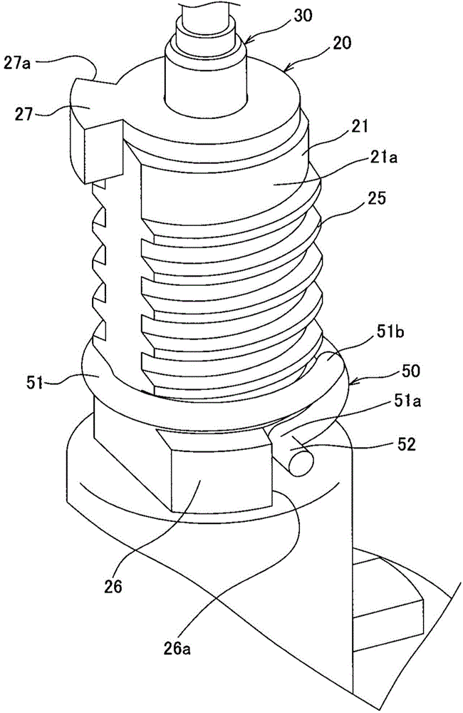
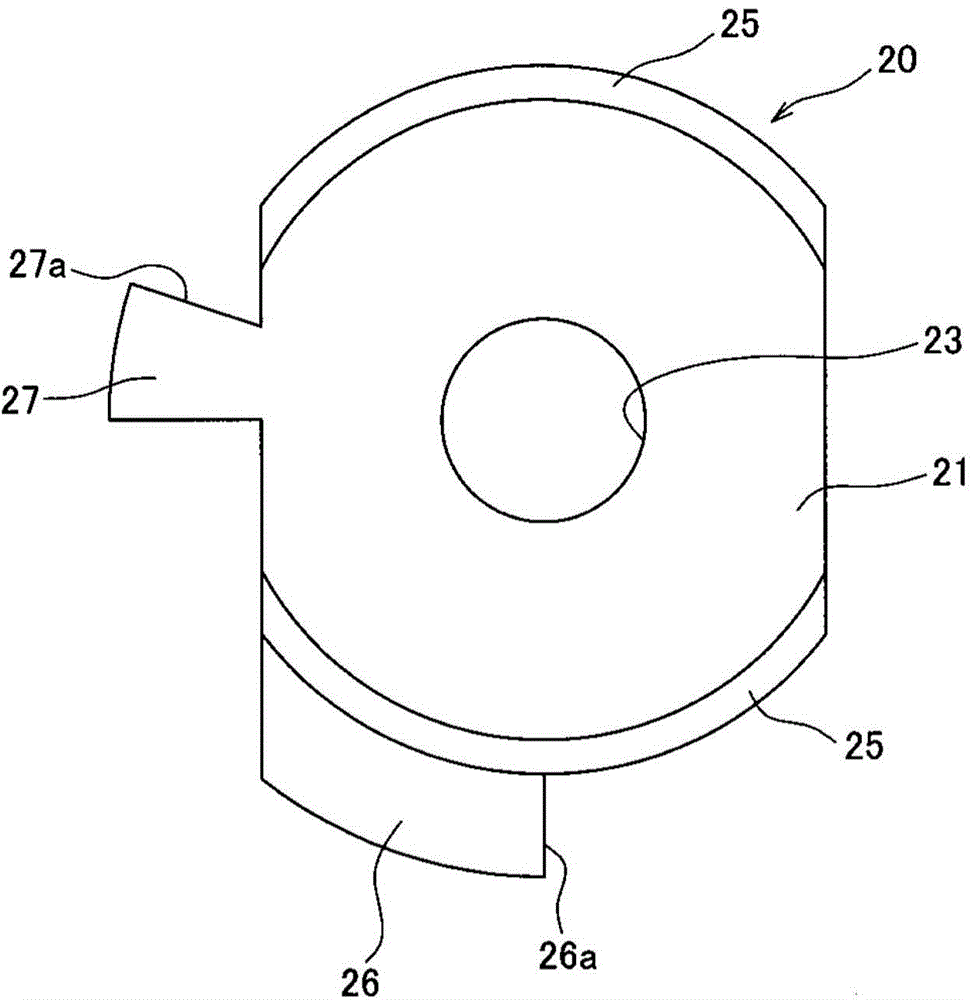
[0045] figure 1 It is a longitudinal sectional view seen from the front direction of the electric valve which concerns on 1st Embodiment of this invention. figure 2 yes figure 1 A perspective view of the supporting member and coil member of the electric valve. image 3 yes figure 2 A top view of the support components. Figure 4 yes figure 2 A perspective view of the coil assembly. Figure 5 yes figure 1 A vertical cross-sectional view of the magnetic rotor included in the electric valve. Figure 6 yes Figure 5 Cutaway perspective view of the magnetic rotor. Figure 7 It is a figure showing the state where the claw part of the coil part hits the valve closing stopper protrusion of the support part, Figure 7 (a) is a figure seen from the back direction, Figure 7 (b) is a figure seen from the side direction. In additio...

no. 2 approach

[0082] Below, refer to Figure 8 ~ Figure 10 An electric valve according to a second embodiment of the present invention will be described.

[0083] Figure 8 It is a longitudinal sectional view seen from the front direction of the electric valve concerning 2nd Embodiment of this invention. Figure 9 yes Figure 8 A perspective view of the coil part included in the electric valve. Figure 10 It means that the claw part of the coil part touches the Figure 8 The diagram of the state of the limit wire body of the guide part of the electric valve, Figure 10 (a) is a figure seen from the front direction, Figure 10 (b) is a figure seen from the side direction. In addition, concepts such as "up and down" in the following descriptions indicate directions and Figure 8 The directions correspond to each other, and represent the relative positional relationship of each component, not the absolute positional relationship.

[0084] Such as Figure 8 As shown, this electric valv...


PUM


Abstract

The invention provides an electric valve that can inhibit uneven sound produced during control over a fixed base point. A coil part (50) of the electric valve (1) is integrally equipped with a coil portion (51) and a claw portion (52), wherein the coil portion can be in threaded combination with a guide rail (25) in a rotary manner, and the claw portion protrudes outwards in a radial direction from one end (51a) of the coil portion (51). A protruding bar (67) fixedly arranged on a magnetic rotor (62) presses the claw portion (52) in a way that the protruding bar rotates along with the magnetic rotor (62) to enable the coil part (50) to rotate. The claw portion (52) comes into contact with a floor-limit limit surface (26a) arranged close to the lower end portion (25a) of the guide rail (25) to limit rotation of the coil part (50). Moreover, when the claw portion (52) comes into contact with the floor-limit limit surface (26a), a claw abut surface (67a), abutting against the claw portion (52), of the protruding bar (67) is formed to tilt relative to the floor-limit limit surface (26a) if the claw portion is viewed in the radial direction of the guide rail (25).

Description

technical field [0001] The present invention relates to, for example, an electric valve used for an expansion valve or the like that controls the flow rate of refrigerant in a refrigeration cycle. Background technique [0002] In the past, in the refrigeration cycle, an expansion valve was installed between the outdoor heat exchanger and the indoor heat exchanger. In the cooling mode, the refrigerant from the outdoor heat exchanger expands in the expansion valve and is guided to the indoor heat exchanger to generate heat. In mode, the refrigerant from the indoor heat exchanger expands in the expansion valve and is directed to the outdoor heat exchanger. As such an expansion valve, various electric valves for controlling the flow rate of refrigerant have been proposed so as to be compatible with normal operation, defrost operation, dehumidification operation, and the like. [0003] Such an electric valve includes, for example, a stopper mechanism for restricting the movement...

Claims


Application Information

Patent Timeline
Patent Type & Authority Applications(China)
IPC IPC(8): F16K31/06F25B41/06
CPCF16K31/0655F25B41/30Y02B30/70
Inventor 中川大树
Owner SAGINOMIYA SEISAKUSHO INC
Why Eureka
Try Eureka