
Light source module

A light source module and point light source technology, applied in the field of optical modules, can solve the problems of difficult alignment between microstructures and light-emitting diodes, increase product costs, etc., and achieve the goal of improving uneven light distribution, good uniformity, and improving energy distribution uniformity Effect

Active Publication Date: 2017-05-17
NANO PRECISION TAIWAN LTD
View PDF9 Cites 0 Cited by
  • Summary
  • Abstract
  • Description
  • Claims
  • Application Information

AI Technical Summary

Problems solved by technology

However, this method will increase the difficulty in the research and development and production of the structure design of the light guide plate 110, and the alignment between the microstructure and the light-emitting diodes will not be easy, which will increase the product cost.

Method used


Image

  • Light source module
  • Light source module
  • Light source module

Examples


Embodiment Construction

[0034] The aforementioned and other technical content, features and effects of the present invention will be clearly presented in the following detailed description of preferred embodiments with accompanying drawings. The directional terms mentioned in the following embodiments, such as: up, down, left, right, front or back, etc., are only referring to the directions of the drawings. Accordingly, the directional terms are used to illustrate and not to limit the invention.

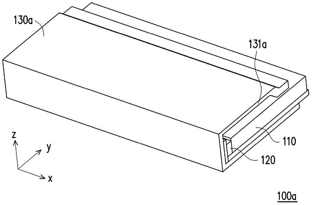
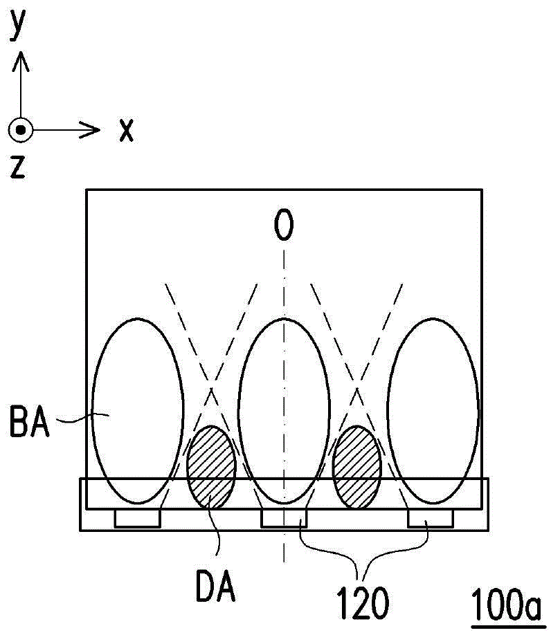
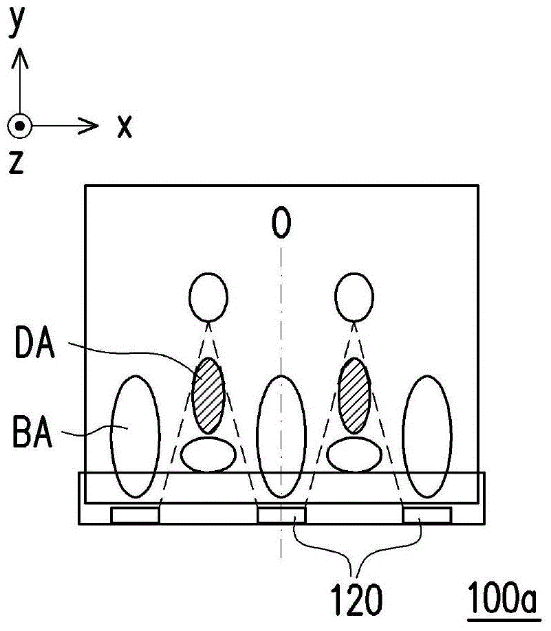
[0035] Figure 2A It is a three-dimensional schematic diagram of a light source module 100 according to an embodiment of the present invention. Figure 2B yes Figure 2A Schematic diagram of the light path on the section A-A' of the light source module of the embodiment. Figure 2C yes Figure 2A Schematic diagram of the light path on the cross-section of the light source module B-B' of the embodiment. Please refer to Figure 2A , in this embodiment, the light source module 100 includes a light guide plat...


PUM


Abstract

The invention discloses a light source module. The light source module comprises a light guide plate, at least one lighting element and a lampshade; the light guide plate is equipped with a first surface, a second surface and a light incoming surface; the lighting element is arranged beside the light incoming surface and equipped with a light outgoing surface which faces the light incoming surface; the lampshade covers the lighting element and one end of the light guide plate, close to the light incoming surface; the lampshade comprises a side plate and an upper plate; the lighting element is arranged between the side plate and the light incoming surface; the upper plate is equipped with a first end, a second end relative to the first end, and at least one convex surface; the upper plate is connected with the side plate through the first end; the upper plate covers the lighting element and the part of the first surface, close to the light incoming surface; the convex surface is positioned right above the lighting element and protrudes toward the lighting element; the convex surface extends from one side of the upper plate, close to the first end to the second end. The light source module provides a high-uniformity surface light source.

Description

technical field [0001] The present invention relates to an optical module, and in particular to a light source module. Background technique [0002] With the development of photoelectric technology, the cold cathode fluorescent lamp (cold cathode fluorescent lamp, CCFL) arranged on the side of the light guide plate in the prior art can be replaced by light-emitting diode (light-emitting diode, LED) light bar (light bar) replaced. Since the light emitting diode has the advantages of long service life, low power consumption, and fast response, the performance and service life of the light source module using the light emitting diode as the light source can be improved. [0003] However, due to the directivity of the light emitted by the light emitting diodes, in the area of ​​the light guide plate close to the light emitting diodes, the light received near the optical axis of the light emitting diodes (that is, facing the light emitting diodes) receives more light and forms a...

Claims


Application Information

Patent Timeline
Patent Type & Authority Patents(China)
IPC IPC(8): F21K9/237F21K9/61F21V3/04F21Y115/10
CPCF21V3/04
Inventor 林锦明李奎稷吴文雄
Owner NANO PRECISION TAIWAN LTD
Learn More