
Diffractive optical element and optical equipment

A diffractive optical element and optical microstructure technology, applied in the field of optical diffraction, can solve the problems of uneven energy distribution of diffracted optical signals and large energy loss of diffracted optical signals, and achieve the effect of improving the uniformity of energy distribution and reducing energy loss

Active Publication Date: 2021-08-31
NANCHANG OUFEI BIOLOGICAL IDENTIFICATION TECH
View PDF16 Cites 2 Cited by
  • Summary
  • Abstract
  • Description
  • Claims
  • Application Information

AI Technical Summary

Problems solved by technology

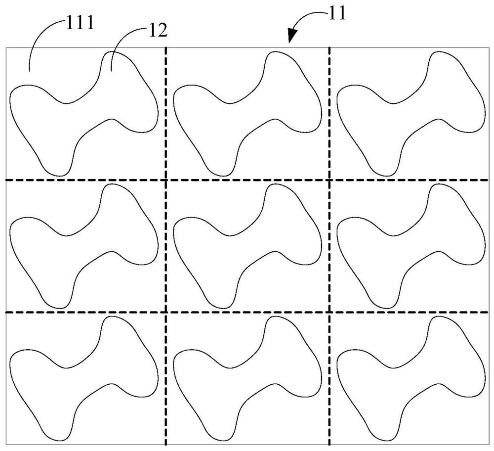
[0003] Embodiments of the present invention provide a diffractive optical element and optical equipment, which are used to solve the problem of large energy loss of diffracted optical signals or uneven energy distribution between diffracted optical signals in the prior art when diffractive optical elements perform diffraction

Method used


Image

  • Diffractive optical element and optical equipment
  • Diffractive optical element and optical equipment
  • Diffractive optical element and optical equipment

Examples


Embodiment Construction

[0048] The following will clearly and completely describe the technical solutions in the embodiments of the present invention with reference to the accompanying drawings in the embodiments of the present invention. Obviously, the described embodiments are some of the embodiments of the present invention, but not all of them. Based on the embodiments of the present invention, all other embodiments obtained by persons of ordinary skill in the art without creative efforts fall within the protection scope of the present invention.

[0049] The terms "first" and "second" in the specification and claims of the present invention are used to distinguish different objects, rather than to describe a specific order of objects. For example, a first end, a second end, etc. are used to distinguish different ends, not to describe a specific order of the ends.

[0050] The terms "comprising" and "having" and any variations thereof in the embodiments of the present invention are intended to co...


PUM

PropertyMeasurementUnit
thicknessaaaaaaaaaa
refractive indexaaaaaaaaaa

Abstract

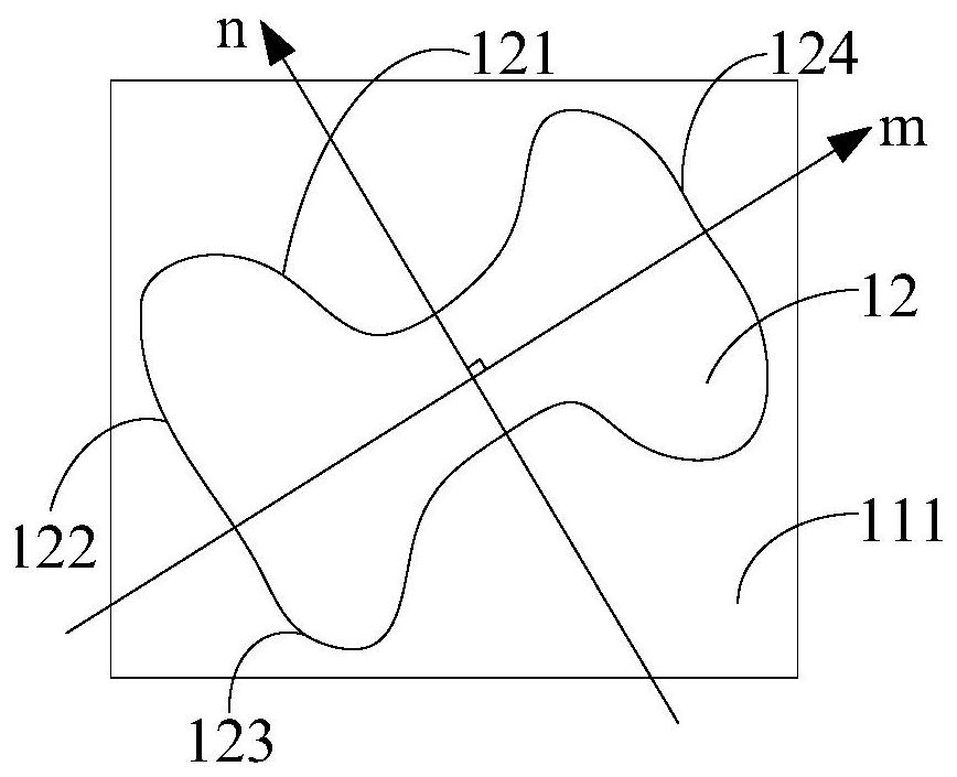
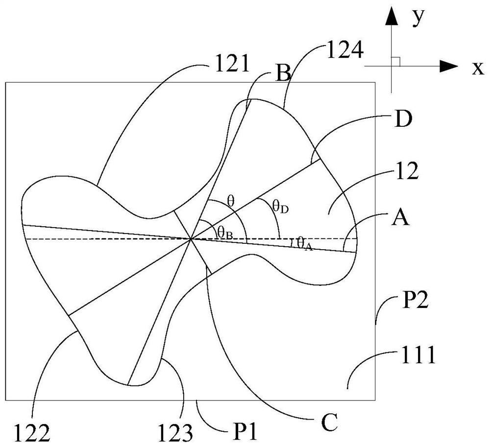
The embodiment of the invention discloses a diffractive optical element and optical equipment, which are applied to the technical field of optical diffraction. The diffractive optical element comprises a substrate and a plurality of optical microstructures. The projection contour of the optical microstructures along the direction vertical to the substrate comprises a first boundary and a third boundary which are oppositely arranged along a first direction, and a second boundary and a fourth boundary which are oppositely arranged in the second direction. The first boundary, the second boundary, the third boundary and the fourth boundary are smoothly connected in sequence; the distance between the first boundary and the third boundary along the first direction is gradually reduced and then gradually increased; the size parameter of each optical microstructure satisfies at least one of the following conditions that the parameter is greater than or equal to 0.228; and the parameter is greater than or equal to 0.684, wherein C is the minimum size of each optical microstructure along the second direction; X is the diagonal dimension of the rectangular setting area corresponding to each optical microstructure; and D is the size of each optical microstructure in the direction of the perpendicular bisector corresponding to the line segment with the minimum size in the second direction.

Description

technical field [0001] Embodiments of the present invention relate to the technical field of optical diffraction, and in particular, to a diffractive optical element and an optical device. Background technique [0002] At present, in the process of depth detection or three-dimensional detection through Time of Flight (TOF) or structured light, it is necessary to diffract the emitted light source signal through a diffractive optical element (DOE) to obtain multiple The beam diffracted light signal is calculated. When the existing diffractive optical element performs diffraction, there is a problem that the energy loss of the diffracted optical signal is large, or the energy distribution among the diffracted optical signals is not uniform. Contents of the invention [0003] Embodiments of the present invention provide a diffractive optical element and optical equipment, which are used to solve the problem of large energy loss of diffracted optical signals or uneven energy d...

Claims


Application Information

Patent Timeline
Patent Type & Authority Applications(China)
IPC IPC(8): G02B27/42
CPCG02B27/4233
Inventor 鞠晓山冯坤亮李宗政成纯森
Owner NANCHANG OUFEI BIOLOGICAL IDENTIFICATION TECH
Learn More