Switch protective housing structure

A protective shell and switch technology, applied in the direction of electrical switches, electrical components, circuits, etc., can solve the problems of no novelty, single and boring overall structure, etc., and achieve the effect of novel structure and convenient use.

Inactive Publication Date: 2015-06-03
SHAANXI DONGXIAN YONGYI ELECTROMECHANICAL TECH
View PDF0 Cites 6 Cited by
  • Summary
  • Abstract
  • Description
  • Claims
  • Application Information

AI Technical Summary

Problems solved by technology

[0002] The shape of the existing switch protective shell is relatively common, but the overall structure is single and boring, and there is no novelty

Method used


Image

  • Switch protective housing structure

Examples


Embodiment Construction

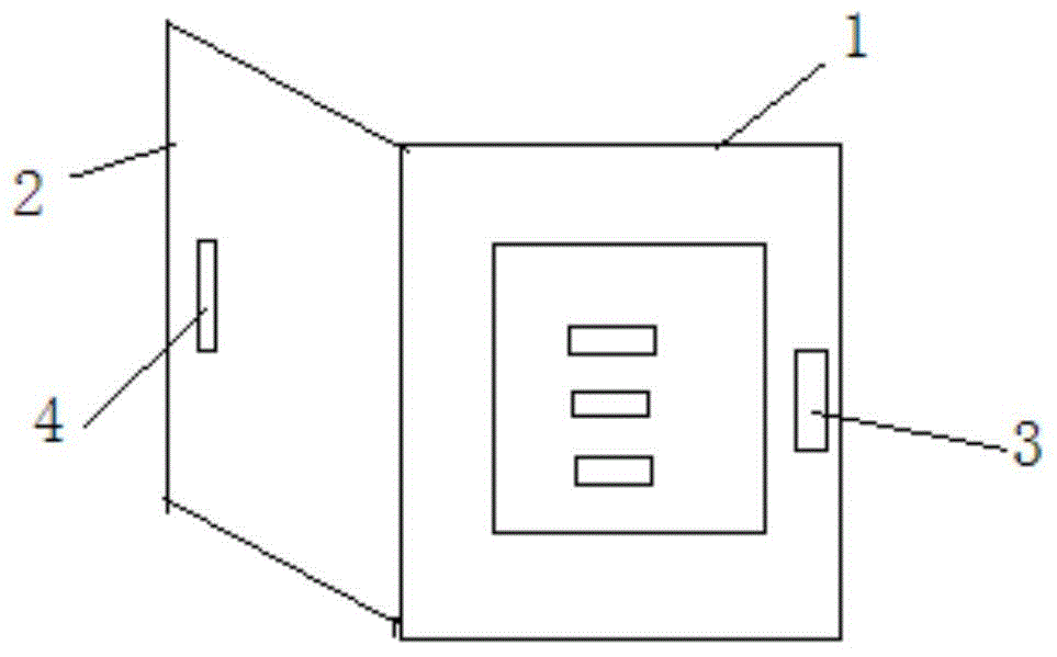
[0008] The present invention will be described in detail below in conjunction with the accompanying drawings.

[0009] Referring to the accompanying drawings, a switch protective shell structure includes a switch base plate 1 and a switch panel 2, one side of the switch panel 2 and the switch base plate 1 is connected by a hinge, a second magnet 4 is provided on the switch panel 2, and a second magnet 4 is arranged on the switch base plate 1. The corresponding position is provided with a first magnet 3, when the switch panel 2 is covered on the switch bottom plate 1, the first magnet 3 and the second magnet 4 are sucked tightly. The invention adopts the principle of two magnets attracting each other, does not need to design a buckle structure, has a novel structure, and is convenient to use.


PUM


Abstract

The invention discloses a switch protective housing structure which comprises a switch bottom plate and a switch panel, wherein one edge of the switch panel is connected with one edge of the switch bottom plate through a hinge; the switch panel is provided with a second magnet; a first magnet is arranged in a corresponding position of the switch bottom plate; when the switch bottom plate is covered with the switch panel, the first magnet and the second magnet attract tightly. According to a principle that two magnets attract, a buckle structure dose not need to be designed, and therefore, the switch protective housing structure is novel in structure and convenient to use.

Description

technical field [0001] The invention relates to a switch protection shell structure. Background technique [0002] The shape of the existing switch protective shell is relatively common, but the overall structure is single and boring, and there is no novelty. Contents of the invention [0003] In order to overcome the above-mentioned shortcomings of the prior art, the object of the present invention is to provide a switch protective shell structure, which is novel in structure and easy to use. [0004] In order to achieve the above object, the technical scheme that the present invention takes is: [0005] A switch protective shell structure, including a switch base plate 1 and a switch panel 2, one side of the switch panel 2 and the switch base plate 1 is connected by a hinge, a second magnet 4 is provided on the switch panel 2, and a second magnet 4 is provided on the corresponding position of the switch base plate 1. There is a first magnet 3, and when the switch panel...

Claims


Application Information

Patent Timeline
Patent Type & Authority Applications(China)
IPC IPC(8): H01H9/02
CPCH01H9/02
Inventor 杜录贤
Owner SHAANXI DONGXIAN YONGYI ELECTROMECHANICAL TECH
Why Eureka
Try Eureka