Usage method for turning machining and locating device of threaded shaft

A technology for positioning devices and threaded shafts, applied in positioning devices, metal processing equipment, metal processing machinery parts, etc., can solve problems such as damage to external threads, and achieve the effects of high positioning processing accuracy, easy operation, and simple structure

Inactive Publication Date: 2015-06-17
WUXI MAAN STEEL CASTING FOUNDRY
View PDF0 Cites 0 Cited by
  • Summary
  • Abstract
  • Description
  • Claims
  • Application Information

AI Technical Summary

Problems solved by technology

[0002] The threaded shaft refers to the shaft with external thread on the outer circumference. When the shaft is turned or the outer circle is processed, the shaft is usually clamped on the three-jaw chuck of the lathe, but for the threaded shaft, this clamping method Can cause serious damage to the external thread of the threaded shaft

Method used


Image

  • Usage method for turning machining and locating device of threaded shaft
  • Usage method for turning machining and locating device of threaded shaft
  • Usage method for turning machining and locating device of threaded shaft

Examples


Embodiment Construction

[0016] The specific implementation manner of the present invention will be described below in conjunction with the accompanying drawings.

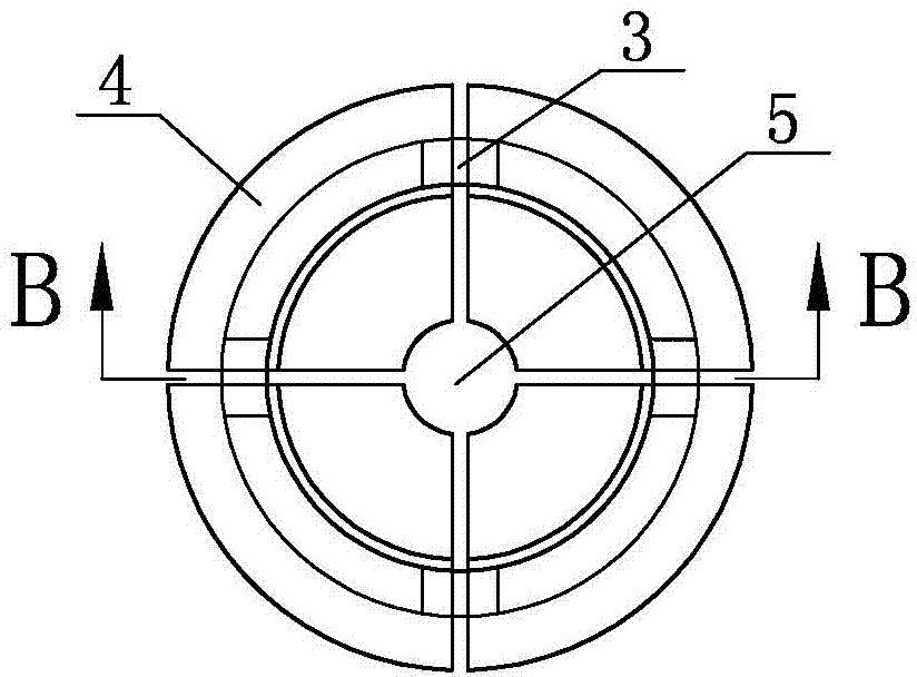
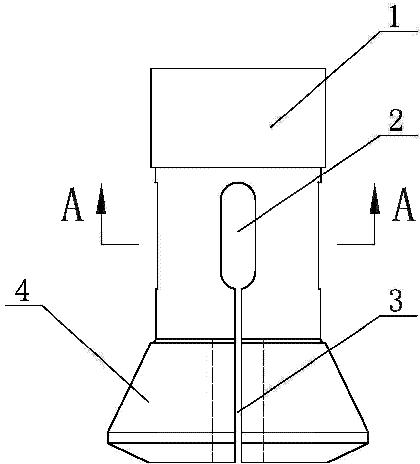
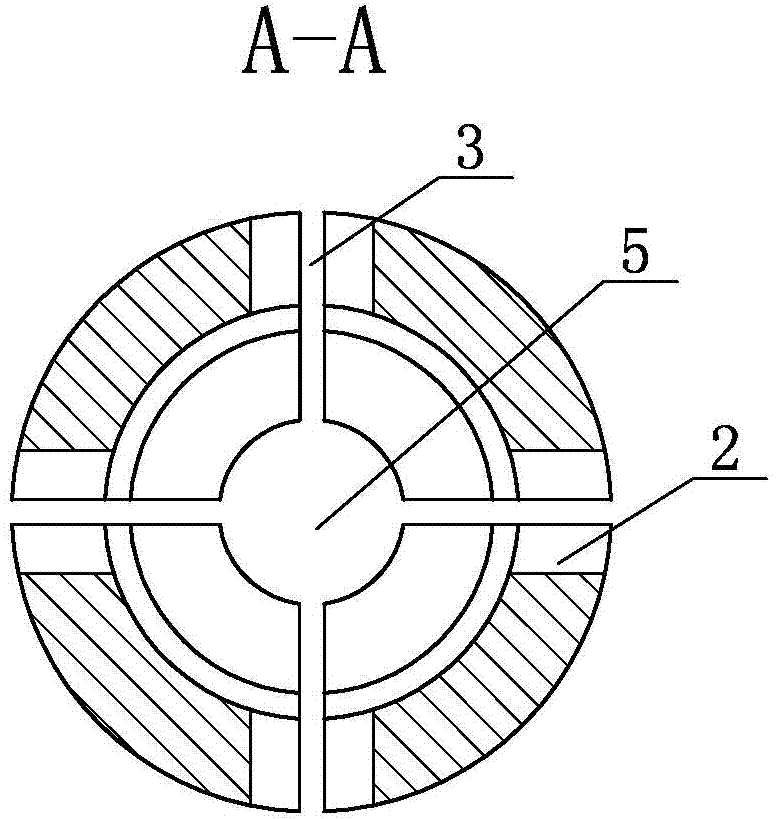
[0017] Such as Figure 1 to Figure 5 As shown, the present invention includes a positioning sleeve, the positioning sleeve includes a clamping section 1 and a tapered section 4, the clamping section 1 has an internal thread, which can cooperate with the external thread of the threaded section 7 of the threaded shaft, and the tapered section 4 There is an external thread on the tapered outer circle; there is an elongated hole 2 on the circumference between the clamping section 1 and the tapered section 4, and a connecting seam 3 is opened from the bottom of the elongated hole 2 to the end surface of the tapered section 4 , the width of the connecting seam 3 is from the circumferential surface of the positioning sleeve to the inner wall of the central hole 5 of the positioning sleeve, and the connecting seam 3 divides the positioning sleeve ...


PUM


Abstract

The invention relates to a usage method for a turning machining and locating device of a threaded shaft. The method comprises the steps that 1, a threaded shaft is installed in a locating sleeve to enable a section, with an outer thread, of the threaded shaft to be matched with a clamping section of the locating sleeve; 2, the clamping section of the locating sleeve is installed on a three-jaw chuck of a machine tool; 3, a clamping nut is screwed tightly, so that a cone-shaped section of the locating sleeve clamps a section to be machined of the threaded shaft; 4, machining is conducted on the threaded shaft. The usage method for the turning machining and locating device of the threaded shaft has the advantages of being simple in structure, simple and convenient to operate and high in locating and machining precision.

Description

technical field [0001] The invention relates to the technical field of tooling fixtures, in particular to a method for using a positioning tooling for turning a shaft with an external thread. Background technique [0002] The threaded shaft refers to the shaft with external thread on the outer circumference. When the shaft is turned or the outer circle is processed, the shaft is usually clamped on the three-jaw chuck of the lathe, but for the threaded shaft, this clamping method Serious damage to the external thread of the threaded shaft will result. Contents of the invention [0003] The present invention aims at the above-mentioned problems in the prior art, and provides a method for using a positioning device for threaded shaft turning, which has a simple structure, easy operation, and high positioning processing precision. [0004] The technical scheme adopted in the present invention is as follows: [0005] The method for using the positioning device for threaded sh...

Claims


Application Information

Patent Timeline
Patent Type & Authority Applications(China)
IPC IPC(8): B23Q3/00
CPCB23Q3/12B23B1/00
Inventor 雷琴
Owner WUXI MAAN STEEL CASTING FOUNDRY
Why Eureka
Try Eureka