
An automatic shearing device for steel plates

A technology of shearing device and steel plate, applied in the field of machinery, can solve the problems of low degree of automation, complicated operation, huge volume, etc., and achieve the effect of improving shearing quality, reducing labor intensity and simplifying processing procedures

Active Publication Date: 2020-10-09
嘉善优耐特滑动轴承厂
View PDF9 Cites 0 Cited by
  • Summary
  • Abstract
  • Description
  • Claims
  • Application Information

AI Technical Summary

Problems solved by technology

However, the traditional steel plate shearing device has a complex structure and a large volume. During use, it is necessary to unwind the coiled steel plate through the unwinding device first, and then use the flattening device to initially flatten the steel plate before shearing. The operation is complicated, the degree of automation is low, and the labor intensity of the workers is high; during the cutting process, it is necessary to equip a shearing knife with a length suitable for the width of the steel plate, and the processing cost is high, which is not conducive to the long-term development of the enterprise

Method used


Image

  • An automatic shearing device for steel plates
  • An automatic shearing device for steel plates
  • An automatic shearing device for steel plates

Examples


Embodiment Construction

[0016] In order to make the technical means, creative features, goals and effects achieved by the present invention easy to understand, the present invention will be further described below in conjunction with specific embodiments.

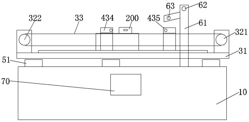
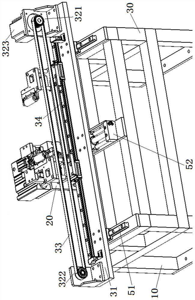
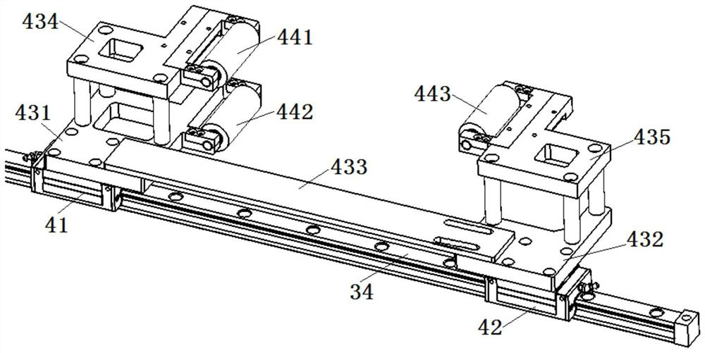
[0017] see Figure 1 to Figure 4 , an automatic steel plate shearing device according to the present invention includes a workbench 10 , a frame block 20 and a frame 30 . Both the frame block 20 and the frame frame 30 are fixedly mounted on the top of the workbench 10 , and the frame frame 30 is disposed on the front side of the frame block 20 . The stand 30 is provided with a clamping mechanism, and the clamping mechanism includes a transverse plate 31 , and the transverse plate 31 is arranged on the top of the stand 30 . The left and right ends of the transverse plate 31 are respectively provided with a first wheel seat 321 and a second wheel seat 322, and the first wheel seat 321 and the second wheel seat 322 are respectively connected with a ...


PUM


Abstract

The invention discloses an automatic shearing device for a steel plate. The automatic shearing device comprises a workbench, a frame block and a stand. The stand is provided with a clamping mechanism.The clamping mechanism comprises a transverse plate, a driving belt, an X-axis sliding rail and a sliding mechanism. The sliding mechanism comprises two sliding sleeves capable of sliding oppositely.The two sliding sleeves are provided with a first roller shaft, a second roller shaft and a third roller shaft. The frame block is provided with a first air cylinder with the movable end being provided with an L-shaped mounting plate. A clamping cylinder and a vertical plate with a horizontal sliding groove are fixed to the top face of the L-shaped mounting plate. A fixing block and a sliding block are arranged in the horizontal sliding groove. The front end of the fixing block and the front end of the sliding block are connected with an L-shaped first clamping plate and an L-shaped second clamping plate correspondingly. A shearing cylinder used for driving a shear body to operate is arranged above the clamping cylinder. The automatic shearing device for the steel plate is compact in structure and convenient to use, the steel plate can be cut automatically and the labor intensity of workers is greatly relieved.

Description

technical field [0001] The invention relates to the field of machinery, in particular to an automatic shearing device for steel plates. Background technique [0002] In the process of mechanical production and processing, it is often necessary to shear the steel plate and then perform subsequent processing. However, the traditional steel plate shearing device has a complex structure and a large volume. During use, it is necessary to unwind the coiled steel plate through the unwinding device first, and then use the flattening device to initially flatten the steel plate before shearing. The operation is complicated, the degree of automation is low, and the labor intensity of the workers is high; the shearing knife whose length is suitable for the width of the steel plate needs to be equipped during the shearing process, and the processing cost is high, which is not conducive to the long-term development of the enterprise. Contents of the invention [0003] The object of the...

Claims


Application Information

Patent Timeline
Patent Type & Authority Patents(China)
IPC IPC(8): B23D15/06B23D15/14B23D33/02B21D1/02B21D43/09B21D43/22
CPCB21D1/02B21D43/09B21D43/22B23D15/06B23D15/14B23D33/02
Inventor 张红杰
Owner 嘉善优耐特滑动轴承厂
Learn More