Container and steel floor chassis thereof

A technology for steel floors and containers, applied in the field of containers, can solve the problems of easy deformation, high cost, low manufacturing efficiency, etc., and achieve the effects of reducing self-weight, improving strength, and reducing labor costs

Inactive Publication Date: 2015-06-17
DALIAN CIMC SPECIAL LOGISTICS EQUIP CO LTD
View PDF6 Cites 3 Cited by
  • Summary
  • Abstract
  • Description
  • Claims
  • Application Information

AI Technical Summary

Problems solved by technology

[0004] The invention provides a container steel floor underframe and a container using the steel floor underframe to solve the problems of low manufacturing efficiency, high cost and easy deformation of the existing steel floor underframe

Method used


Image

  • Container and steel floor chassis thereof
  • Container and steel floor chassis thereof
  • Container and steel floor chassis thereof

Examples


Embodiment Construction

[0021] In order to further illustrate the principle and structure of the present invention, preferred embodiments of the present invention will now be described in detail with reference to the accompanying drawings.

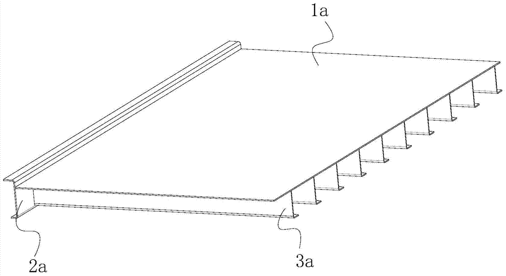
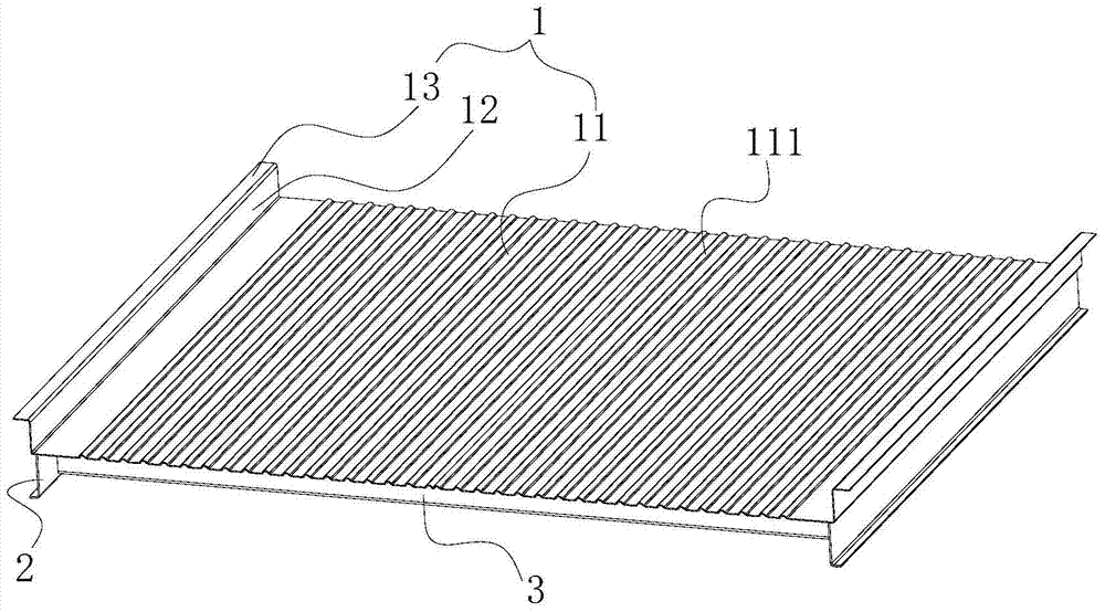
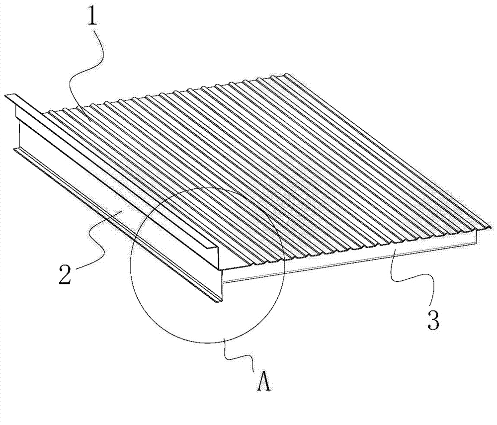
[0022] see Figure 2 to Figure 4 , the present invention provides a container steel floor chassis, comprising a steel floor 1, bottom side beams 2 and bottom cross beams 3; , its height compared to figure 1 The existing structure shown is smaller, the bottom side beam 2 is L-shaped, the upper end of one arm is welded and fixed to the lower surface of the steel floor 1, and the other arm faces the outside of the steel floor 1; the bottom beam 3 is also located on the steel floor 1 Below, there are multiple longitudinally spaced beams along the steel floor 1. The upper end of the bottom beam 3 is welded and fixed to the lower surface of the steel floor 1, and the two ends of the bottom beam 3 are welded and fixed to the two bottom side beams 2 respectively.

[00...


PUM


Abstract

The invention discloses a container and a steel floor chassis thereof. The chassis comprises a steel floor, bottom side beams positioned at the transverse two sides of the steel floor, and multiple bottom cross beams longitudinally arranged below the steel floor and fixedly connected with the steel floor, wherein the two ends of the bottom cross beams are fixedly connected with the two bottom side beams; the steel floor comprises a floor body, a first bent edge upwards bent from the two sides of the floor body, and a second bent edge outwards vertically bent from the upper end of the first bent edge; longitudinal strip-shaped reinforcing ribs are upwards projected on the floor body; multiple reinforcing ribs are transversely arranged on the floor body; the height of the first bent edge is greater than the height of the reinforcing ribs; and the upper surface of the second bent edge is used for fixing with container side plates. The container and the steel floor chassis thereof can reduce the welding deformation, and have the advantages of high strength, small deadweight, low cost, high machining efficiency and high product reliability.

Description

technical field [0001] The invention relates to the field of containers, in particular to a container steel floor underframe and a container using the steel floor underframe. Background technique [0002] Common dry container chassis structures are mainly divided into two types. One is that the bottom side beams and bottom beams are welded into a steel structure, and then the wooden floor is screwed to the bottom beams. This structure is currently the most widely used container bottom. Frame structure, but this structure has the following disadvantages: (1) It needs to use a large number of floor nails to connect with the bottom beam. After drilling, arranging nails, locking nails and cleaning, the process is complicated and the labor cost is high. (2) The wooden floor and the bottom beam are connected at points. The floor and the bottom beam cannot be an integral force-bearing member. The moment of inertia and bending section coefficient of the bottom beam are relatively lo...

Claims


Application Information

Patent Timeline
Patent Type & Authority Applications(China)
IPC IPC(8): B65D90/02B65D88/52
CPCB65D88/02B65D90/02
Inventor 姚谷黎泽深孔河清姚学文赵建刚
Owner DALIAN CIMC SPECIAL LOGISTICS EQUIP CO LTD
Why Eureka
Try Eureka