Laser receiving optical axis and visible light optical axis parallelism adjustment system and adjustment method

A laser receiving and visible light technology, applied in the field of optical detection, can solve the problems of low precision, poor stability, large environmental influence factors, etc., and achieve the effect of improving precision and efficiency

Active Publication Date: 2015-06-17
CHINA NORTH VEHICLE RES INST
View PDF8 Cites 16 Cited by
  • Summary
  • Abstract
  • Description
  • Claims
  • Application Information

AI Technical Summary

Problems solved by technology

[0009] The disadvantage of this adjustment method is that it cannot be seen visually,

Method used


Image

  • Laser receiving optical axis and visible light optical axis parallelism adjustment system and adjustment method
  • Laser receiving optical axis and visible light optical axis parallelism adjustment system and adjustment method
  • Laser receiving optical axis and visible light optical axis parallelism adjustment system and adjustment method

Examples


Embodiment 1

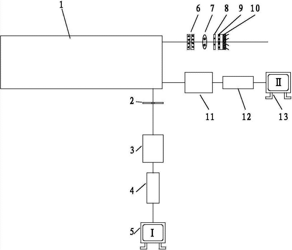
[0043] refer to figure 2 and image 3 As shown, the system for adjusting the parallelism between the laser receiving optical axis and the visible light optical axis in this embodiment includes the following components:

[0044] A reflective collimator 1 placed on a fixed workbench;

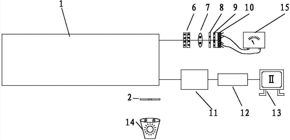
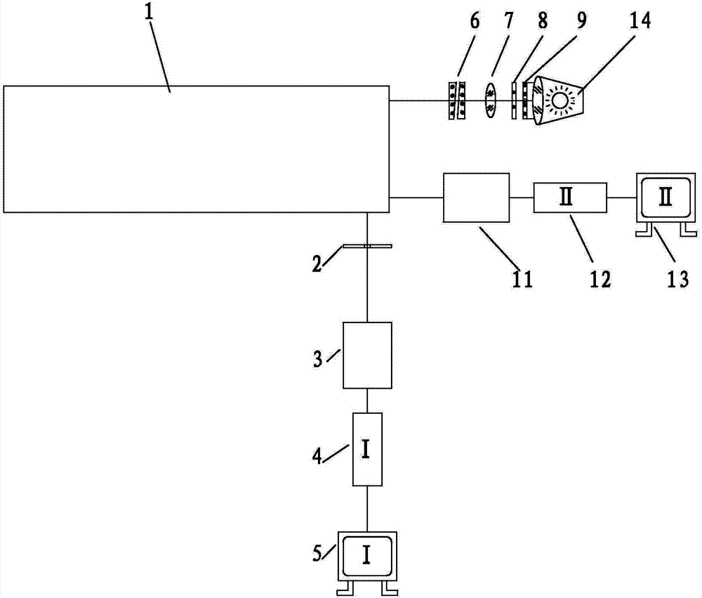
[0045]The laser receiving channel, aligned with the reflective collimator 1, includes a coaxially arranged optical wedge 6, a receiving objective lens 7, an optical filter 8, a small hole glass 9 and an avalanche tube 10; the optical wedge 6 has two pieces; because The pinhole glass 9 and the avalanche tube 10 are usually made together, and the relative position of the two is particularly important, which determines whether the imaging can fall on the photosensitive surface of the avalanche tube 10. When adjusting, it is necessary to use a spotlight 14 to replace the The avalanche tube 10 is described above, so it is only necessary to replace the avalanche tube 10 during adjustment, and continu...

Embodiment 2

[0057] Based on the above-mentioned calibration system, the present invention also provides a method for calibrating the parallelism between the laser receiving optical axis and the visible light axis. On the fixed workbench, the reticle 2 is set as a cross reticle, and the front of the reticle 2 is placed sequentially as the achromatic lens 3 for adjustment, the first CCD camera 4 and the first display 5, and the cross reticle 2 The axial distance with the achromatic lens 3 is the object distance of the achromatic lens, and the axial distance between the achromatic lens 3 and the first CCD camera 4 is the back intercept of the achromatic lens; Align the type collimator 1; then perform adjustment, the adjustment specifically includes the following steps:

[0058] S1: The visible light channel is electronically divided; when the visible light channel includes such as figure 2 When the lens 11, the second CCD camera 12 and the second display 13 are shown, in the step S1, the e...


PUM


Abstract

The invention belongs to the field of optical detection, and discloses a laser receiving optical axis and visible light optical axis parallelism adjustment system and an adjustment method. According to the adjustment system, a visible light and laser dual-band achromatic lens and a dual-channel visualization image are adopted for judging and adjusting the optical axis parallelism. The method comprises the following steps: aligning a visible light optical axis to the center of a reflection-type collimator reticle, transmitting illuminating light beams by adopting a spotlight, enabling the light beams to enter a laser receiving channel, generating an image at an image side of the achromatic lens after the light beams sequentially pass through a collimator and the achromatic lens, transmitting the image to a displayer, observing the image, reading an error of the optical axis parallelism by utilizing the lattice value of the reticle, rotating a receiving optical wedge in front of the laser receiving passage, and collimating the parallelism of the optical axis. By adopting the laser receiving optical axis and visible light optical axis parallelism adjustment system and adjustment method, the parallelism of the laser receiving axis and the visible light optical axis can be effectively adjusted, characteristics such as intuitiveness and visualization can be achieved, and the precision and efficiency for adjusting the optical axis parallelism also can be improved.

Description

technical field [0001] The invention belongs to the field of optical detection, and relates to an adjustment system and an adjustment method for the parallelism between a laser receiving optical axis and a visible light axis. Background technique [0002] The three axes refer to the visible light axis, the laser emitting optical axis and the laser receiving optical axis in the optical system of the laser range finder. The laser range finder requires that the three must be parallel to each other, so that the measured distance is the target distance to be aimed at. The three are determined by the position of each optical part in the optical system, so any change in the position of an optical part will destroy the parallelism of the three axes. The parallelism of the three axes is guaranteed by adjusting each optical system with special optical instruments. If the parallelism of the three axes changes during use or maintenance, it must be re-adjusted. Usually, the optical axi...

Claims


Application Information

Patent Timeline
IPC IPC(8): G01C25/00
CPCG01C25/00
Inventor 田继文刘辉武陈光辉周平朱东刘义郝小健梅林孙瑜朱晶晶高古君朴燕陈海红
Owner CHINA NORTH VEHICLE RES INST
Why Eureka
Try Eureka