A high-voltage equipment box for a rail vehicle

A technology for high-voltage equipment boxes and rail vehicles, applied in the field of rail vehicles, can solve the problems of increasing aerodynamic noise, complex roof structure, influence of roof streamline structure, etc., so as to improve aerodynamic performance, reduce air resistance, and improve aerodynamic performance Effect

Active Publication Date: 2017-06-06
CRRC QINGDAO SIFANG CO LTD +1
View PDF7 Cites 0 Cited by
  • Summary
  • Abstract
  • Description
  • Claims
  • Application Information

AI Technical Summary

Problems solved by technology

[0004] However, adopting the above-mentioned method requires grooves to be provided on the roof, and positioning components for fixing high-voltage equipment such as high-voltage joints are arranged in the grooves, which makes the structure of the roof more complicated; more importantly, the structure of the grooves The carrying space is limited, so it is impossible to install all high-voltage equipment, and the positioning reliability of high-voltage equipment cannot be guaranteed; there are various types of high-voltage equipment, and the volume of each high-voltage equipment is different. When the high-voltage equipment is installed in the groove of the roof, it may Part of the structure of Huicun protrudes from the roof. When there are high-voltage equipment on the roof of each compartment, it will have a great impact on the streamline structure of the roof, thereby increasing aerodynamic noise.
[0005] Furthermore, high-voltage equipment usually needs to transmit the high-voltage electricity obtained by the pantograph to the cabin, and the groove structure on the roof cannot meet this demand. If the high-voltage equipment is built into the groove on the roof, it is necessary to The roof is further processed or a special high-voltage transmission line is set up, which further increases the complexity of the roof structure

Method used


Image

  • A high-voltage equipment box for a rail vehicle
  • A high-voltage equipment box for a rail vehicle
  • A high-voltage equipment box for a rail vehicle

Examples


Embodiment Construction

[0026] The core of the present invention is to provide a high-voltage equipment box for rail vehicles, which can realize the sunken installation of high-voltage equipment, and at the same time reduce the impact on the streamline structure of the roof, thereby reducing air resistance and aerodynamic noise, and improving the aerodynamic performance of the train .

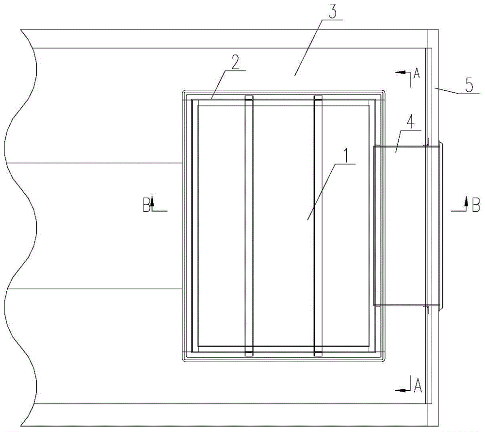
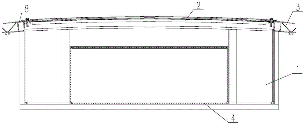
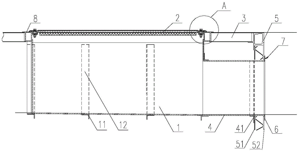
[0027] The present invention provides a high-voltage equipment box of a rail vehicle, which is arranged on the roof 3 of the rail vehicle, and specifically can be integrated on the roof 3, so as to realize "sinking" installation of high-voltage equipment.

[0028] Such as Figure 1-4 As shown, there is a high-voltage equipment box for installing high-voltage equipment on the roof 3 of the rail vehicle, including a box body 1 and a top cover 2 covered on the box body 1, and the box body 1 has a hollow space for accommodating high-voltage equipment. cavity, so that the high-voltage equipment can be installed in the box...


PUM


Abstract

The invention provides a high voltage equipment box for a railway vehicle. Sunken mounting of high voltage equipment can be achieved, meanwhile, the influence on the streamline structure of a vehicle roof is lowered, air resistance and aerodynamic noise are reduced, and the aerodynamic performance of trains is improved. The high voltage equipment box comprises a box body used for mounting the high voltage equipment and a top cover which covers the box body. The box body is embedded in the vehicle roof of the railway vehicle, the top cover is connected with the vehicle roof, and the top face of the top cover is arranged to be in an arc shape matched with the vehicle roof. The high voltage equipment box further comprises a connecting cylinder, one end of the connecting cylinder is communicated with the box body, and the other end of the connecting cylinder extends to an end wall of the railway vehicle and penetrates through the end wall. The box body is embedded in the vehicle roof, and the high voltage equipment is mounted in the box body and cannot protrude out of the vehicle roof, so that the air resistance and the aerodynamic noise are lowered, and the overall aerodynamic performance of the trains is improved. The top cover of the high voltage equipment box is matched with the vehicle roof, the overall streamline structure of the vehicle roof cannot be influenced, and the whole external profile of the vehicle roof is made to meet the requirement of dynamics.

Description

technical field [0001] The invention relates to the technical field of rail vehicles, in particular to a high-voltage equipment box of a rail vehicle. Background technique [0002] At present, the current collection system of traditional trains protrudes from the roof, which has a great impact on the noise inside the train and the noise of the source field. At the same time, it will also have a great impact on the aerodynamic performance of the whole train. [0003] In view of the above situation, structures such as grooves can be provided on the roof of the vehicle in the prior art, so that current collecting equipment such as high-voltage connectors can be installed on the roof, so that the current collecting equipment does not protrude from the roof as much as possible, and the installation of the current collecting equipment is reduced. effect on the aerodynamic performance of the vehicle. [0004] However, adopting the above-mentioned method requires grooves to be set ...

Claims


Application Information

Patent Timeline
Patent Type & Authority Patents(China)
IPC IPC(8): H02B1/46H02B1/28
CPCH02B1/28H02B1/46
Inventor 顾春雷户迎灿陈文宾赵士忠田爱琴鄢桂珍丁叁叁梁建英王晶凯
Owner CRRC QINGDAO SIFANG CO LTD
Why Eureka
Try Eureka