Railway vehicle and roof thereof

A rail vehicle and profile technology, applied in the field of rail vehicles, can solve problems such as noise inside the vehicle, the influence of source field noise, reduce the strength of the roof, and low space utilization, so as to simplify the structure of the car body, improve the strength of the car body, reduce the The effect of the weld

Inactive Publication Date: 2015-06-17
CRRC QINGDAO SIFANG CO LTD +1
View PDF9 Cites 15 Cited by
  • Summary
  • Abstract
  • Description
  • Claims
  • Application Information

AI Technical Summary

Problems solved by technology

[0002] At present, the roof of traditional trains is spliced ​​by multiple profiles, and the number of profiles required is large, so there are more welds on the roof, which reduces the strength of the roof and affects the smoothness of the outer contour of the roof Spend
[0003] Furthermore, each profile is heavy, and the weight of the roof spliced ​​by various profiles is relatively large, which cannot meet the needs of lightweight.
[0004] More importantly, the current collection system of traditional trains, such as pantographs and high-voltage connectors, protrude from the roof, and air conditioners are usually installed on the roof, and the top of the air conditioner also protrudes from the roof, so the air conditioner And the current collection system will have a great impact on the noise inside the car and the source field noise, and will also have a great impact on the aerodynamic performance of the vehicle
[0005] In addition, the interior of the roof usually requires built-in equipment. In order to realize the installation of the built-in equipment, it is usually necessary to weld the mounting seat and other structures on the car body, which is not only inconvenient to install, but also has a low space utilization rate.

Method used


Image

  • Railway vehicle and roof thereof
  • Railway vehicle and roof thereof
  • Railway vehicle and roof thereof

Examples


Embodiment Construction

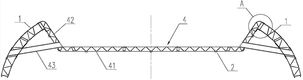
[0030] The core of the present invention is to provide a rail vehicle and its roof, which can realize the sunken installation of current collectors and air conditioners, and at the same time reduce the impact on the streamline structure of the roof, thereby reducing air resistance and aerodynamic noise, and lifting the train. aerodynamic performance.

[0031] The vehicle roof of the present invention will be introduced below with reference to the accompanying drawings, so that those skilled in the art can accurately understand the technical solution of the present invention.

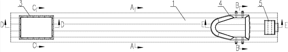
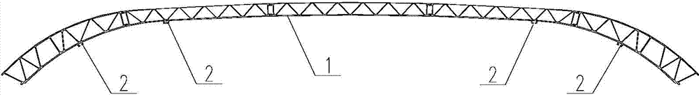
[0032] Such as figure 1 with figure 2 As shown, the roof 1 of the rail vehicle in the present invention includes several hollow profiles, each hollow profile extends longitudinally to cover the longitudinal direction of the entire car body; each hollow profile is spliced ​​horizontally to form the entire roof 1. Specifically, five hollow profiles can be spliced ​​to form the entire roof 1, and a hollo...


PUM


Abstract

The invention provides a railway vehicle and a roof thereof. Sunken installation of a current collector and an air conditioner can be achieved, the influences on a roof streamline structure are reduced, air resistance and aerodynamic noise are lowered, and the aerodynamic performance of a train is improved. The roof comprises multiple transversely-spliced hollow section bars, longitudinally-stretching chutes are formed in the bottom faces of the hollow section bars, and an installation part of built-in equipment is formed. The roof is provided with an air conditioner installation seat, a pantograph installation seat and a high-voltage equipment box which are all embedded in the roof, and the tops of the air conditioner installation seat, the pantograph installation seat and the high-voltage equipment box are each in an arc shape matched with the roof. The roof is formed by splicing the hollow section bars, the chutes are formed in the bottom faces of the hollow section bars, when needed, the built-in equipment enters the roof from the chutes in the roof, and the equipment is hoisted on the roof. The air conditioner installation seat, the pantograph installation seat and the high-voltage equipment box are all embedded in the roof, smooth design of the surface of the roof is achieved, and the aerodynamic performance of the train is effectively improved.

Description

technical field [0001] The invention relates to the technical field of rail vehicles, in particular to a rail vehicle and its roof. Background technique [0002] At present, the roof of traditional trains is spliced ​​by multiple profiles, and the number of profiles required is large, so there are more welds on the roof, which reduces the strength of the roof and affects the smoothness of the outer contour of the roof Spend. [0003] Furthermore, each profile is relatively heavy, so the weight of the vehicle roof spliced ​​by various profiles is relatively large, which cannot meet the requirement of light weight. [0004] More importantly, the current collection system of traditional trains, such as pantographs and high-voltage connectors, protrude from the roof, and air conditioners are usually installed on the roof, and the top of the air conditioner also protrudes from the roof, so the air conditioner And the current collection system will have a great impact on the noi...

Claims


Application Information

Patent Timeline
Patent Type & Authority Applications(China)
IPC IPC(8): B61D17/12
CPCB61D17/12
Inventor 顾春雷户迎灿尚克明陈文宾赵士忠田爱琴梁建英陶桂东
Owner CRRC QINGDAO SIFANG CO LTD
Why Eureka
Try Eureka