Reactive compensation system

A compensation system and control system technology, applied in reactive power compensation, reactive power adjustment/elimination/compensation, AC network circuits, etc., can solve problems such as inability to compensate reactive power, many links of manual participation, and short service life of capacitors , to achieve the effect of good practicability and high precision reactive power compensation

Inactive Publication Date: 2015-06-17
SHANGHAI MUNICIPAL ELECTRIC POWER CO
View PDF3 Cites 0 Cited by
  • Summary
  • Abstract
  • Description
  • Claims
  • Application Information

AI Technical Summary

Problems solved by technology

[0002] At present, most of the standard reactive power compensation equipment in each substation is a power factor controller plus a contactor or a capacitor bank switching method controlled by a capacitor. Due to frequent switching, the life of the capacitor is not long, and because of the need for manual participation Many, not continuous reactive power compensation

Method used


Image

  • Reactive compensation system

Examples


Embodiment Construction

[0014] The present invention will be further described below in conjunction with accompanying drawing.

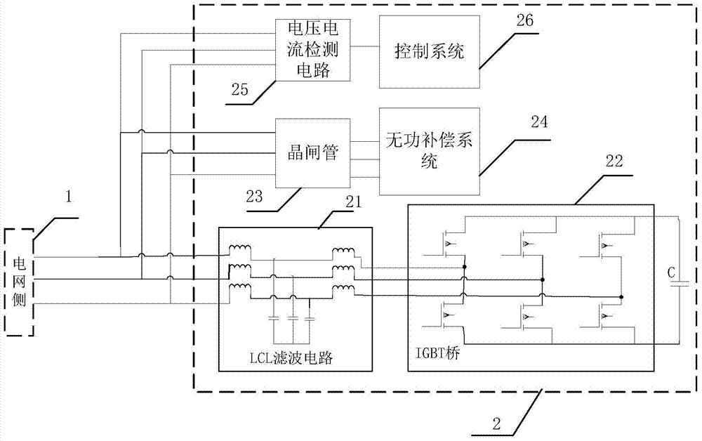
[0015] see figure 1 , a reactive power compensation system 2 of the present invention is externally connected to the power grid side 1, and the reactive power compensation system 2 includes an LCL filter circuit 21, an IGBT bridge 22 and a capacitor C sequentially connected to the power grid side 1, and a thyristor connected to the power grid side 1 in sequence 23 and a reactive power compensation unit 24, a voltage and current detection circuit 25 and a control system 26 sequentially connected to the grid side 1, wherein:

[0016] Both ends of the capacitor C are connected to the IGBT bridge 22;

[0017] The voltage and current detection circuit 25 collects voltage signals and current signals on the grid side, and transmits them to the control system 26; the control system 26 processes the received voltage signals and current signals, and sends control signals to the thyr...


PUM


Abstract

The invention discloses a reactive compensation system. The reactive compensation system comprises an LCL filter circuit, an IGBT bridge, a capacitor, a thyristor, a reactive compensation unit, a voltage and current detection circuit and a control system, wherein the LCL filter circuit, the IGBT bridge and the capacitor are sequentially connected with a power grid side; the thyristor and the reactive compensation unit are sequentially connected with the power grid side; the voltage and current detection circuit and the control system are sequentially connected with the power grid side; the two ends of the capacitor are connected with the IGBT bridge; the voltage and current detection circuit collects voltage signals and current signals of the power grid side and transmits the signals to the control system; the control system processes the received voltage signals and the received current signals and sends control signals to the thyristor and the IGBT bridge respectively according to the processing result. Reactive parameters can be automatically and continuously adjusted according to the collected voltage signals and the collected current signals, and reactive power compensation can be carried out rapidly and highly precisely.

Description

technical field [0001] The invention relates to the field of reactive power compensation, in particular to a reactive power compensation system. Background technique [0002] At present, most of the standard reactive power compensation equipment in each substation is a power factor controller plus a contactor or a capacitor bank switching method controlled by a capacitor. Due to frequent switching, the life of the capacitor is not long, and because of the need for manual participation More, can not continuous reactive power compensation. Therefore, researching a relatively automatic, fast and high-precision compensation system is a problem that the applicant is committed to solving. Contents of the invention [0003] The purpose of the present invention is to overcome the defects of the prior art and provide a reactive power compensation system, which can automatically and continuously adjust reactive power parameters according to the collected voltage and current signals...

Claims


Application Information

Patent Timeline
Patent Type & Authority Applications(China)
IPC IPC(8): H02J3/18
CPCY02E40/30H02J3/1821
Inventor 黄维华秦虹杨素佳宗明何志伟
Owner SHANGHAI MUNICIPAL ELECTRIC POWER CO
Why Eureka
Try Eureka