Reactive power compensation method and device for distributed power supply

A technology of distributed power supply and compensation method, applied in the direction of reactive power compensation, reactive power adjustment/elimination/compensation, etc., can solve problems such as the inability to quickly suppress voltage fluctuations

Inactive Publication Date: 2017-08-18
STATE GRID SHANDONG ELECTRIC POWER +1
View PDF5 Cites 2 Cited by
  • Summary
  • Abstract
  • Description
  • Claims
  • Application Information

AI Technical Summary

Problems solved by technology

[0005] Therefore, the technical problem to be solved by the present invention is to overcome the defect that the existing technology cannot quickly suppress the steep voltage fluctuation caused by the distributed power supply connected to the system, thereby providing a reactive power compensation method for distributed power supply , including the following steps:

Method used


Image

  • Reactive power compensation method and device for distributed power supply
  • Reactive power compensation method and device for distributed power supply
  • Reactive power compensation method and device for distributed power supply

Examples


Embodiment 1

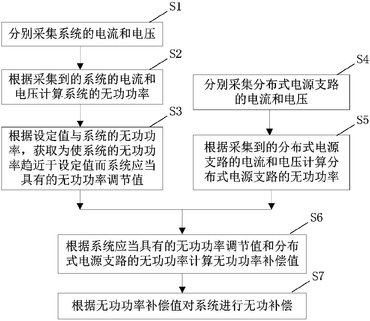
[0136] This embodiment provides a reactive power compensation method for distributed power sources, such as figure 1 shown, including the following steps:

[0137] S1: collect the current and voltage of the system respectively.

[0138] S2: Calculate the reactive power of the system according to the collected current and voltage of the system.

[0139] S3: According to the set value and the reactive power of the system, obtain the reactive power adjustment value that the system should have in order to make the reactive power of the system approach the set value.

[0140] Specifically, the reactive power of the system is subtracted from the set value to obtain a difference, and then the difference is regulated by PI to obtain a reactive power adjustment value.

[0141] S4: collect the current and voltage of the distributed power branch respectively.

[0142] S5: Calculate the reactive power of the distributed power branch according to the collected current and voltage of the...

Embodiment 2

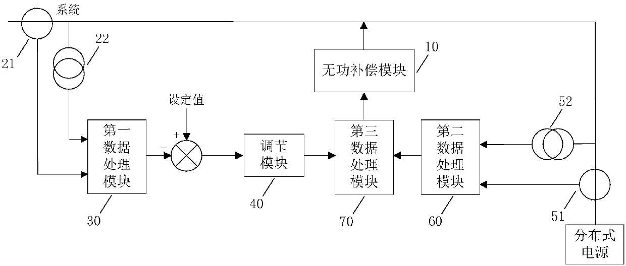
[0185] This embodiment provides a reactive power compensation device for distributed power sources, such as image 3 As shown, it includes a reactive power compensation module 10, which is used to compensate the reactive power of the system according to the reactive power compensation capacity, and also includes a first current acquisition module 21, a first voltage acquisition module 22, a first data processing module 30, a regulating module 40 , a second current acquisition module 51 , a second voltage acquisition module 52 , a second data processing module 60 and a third data processing module 70 .

[0186] The first current collection module 21 and the first voltage collection module 22 are respectively used to collect the current and voltage of the system.

[0187] The first data processing module 30 is configured to calculate the reactive power of the system according to the collected current and voltage of the system.

[0188] The adjustment module 40 is used to obtain...


PUM


Abstract

The invention relates to a reactive power compensation method and device for a distributed power supply. The reactive power compensation method comprises the steps of calculating reactive power of a system according to acquired current and voltage of the system; acquiring a reactive power regulation value which the system is supposed to have in order to enable the reactive power of the system to approach to the set value according to a set value and the reactive power of the system; and calculating reactive power of a distributed power supply branch according to acquired current and voltage of the distributed power supply branch. Compensation is performed on the reactive power of the system, and the voltage and current of the system are acquired in real time to act as feedback values so as to perform real-time regulation, and a closed-loop control system for the reactive power of the system is formed. When reactive power compensation is performed on the system, a reactive power compensation value for the system is enabled to be the difference between a reactive power regulation value of the system and the reactive power of the distributed power supply branch, so that variations in reactive power of the distributed power supply branch are balanced through regulating the reactive power compensation value for the system in real time, reactive power compensation can be performed quickly, and thus voltage fluctuations of the system are suppressed.

Description

technical field [0001] The invention relates to the technical field of power supply and distribution, in particular to a reactive power compensation method and device for a distributed power supply. Background technique [0002] With the development of power generation and power supply and distribution technology, more and more distributed power sources are connected to the power grid. Due to the influence of weather and other factors, distributed power generation has the characteristics of random changes, which will increase the voltage fluctuation of the system when the distributed power generation is connected to the grid system, and the system voltage fluctuation will affect the safe and stable operation of the power system. [0003] In order to suppress system voltage fluctuations, most of the existing adjustment methods for reactive power compensation controllers are to adjust the voltage of the entire system. For example, Chinese patent document CN 102025163 B disclos...

Claims


Application Information

Patent Timeline
Patent Type & Authority Applications(China)
IPC IPC(8): H02J3/18
CPCY02E40/30H02J3/18
Inventor 王萍
Owner STATE GRID SHANDONG ELECTRIC POWER
Why Eureka
Try Eureka