Method and system for inhibiting voltage fluctuation of photovoltaic power station

A photovoltaic power station, voltage fluctuation technology, applied in photovoltaic power generation, AC network voltage adjustment, reactive power compensation, etc., can solve problems such as voltage fluctuation, affecting power quality, and affecting grid voltage flicker coefficient

Active Publication Date: 2016-01-20
SUNGROW POWER SUPPLY CO LTD
View PDF2 Cites 11 Cited by
  • Summary
  • Abstract
  • Description
  • Claims
  • Application Information

AI Technical Summary

Problems solved by technology

[0006] figure 1 When the active power P in the shown photovoltaic power station system changes, the voltage at the PCC will fluctuate, which will affect the power quality of other substations or civil loads connected to the PCC point, especially the flicker coefficient of the grid voltage

Method used


Image

  • Method and system for inhibiting voltage fluctuation of photovoltaic power station
  • Method and system for inhibiting voltage fluctuation of photovoltaic power station
  • Method and system for inhibiting voltage fluctuation of photovoltaic power station

Examples


Embodiment 1

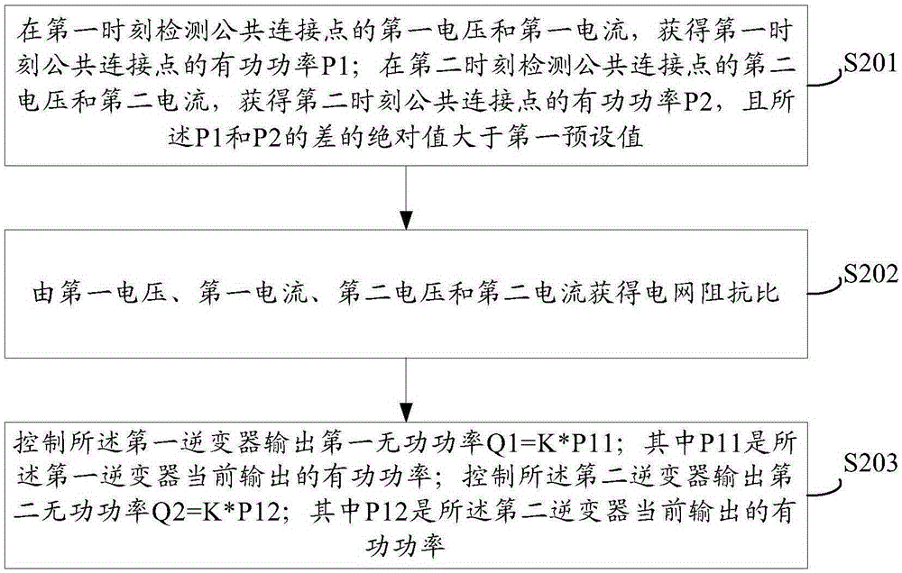
[0055] see figure 2 , which is a flow chart of Embodiment 1 of the method for suppressing voltage fluctuations in photovoltaic power plants provided by the present invention.

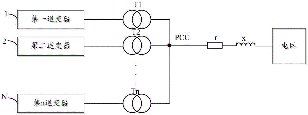
[0056] The method for suppressing voltage fluctuations in a photovoltaic power station provided in this embodiment is applied to a photovoltaic power station system, and the system includes at least the following two inverters: a first inverter and a second inverter; the first inverter passes The first transformer is connected to a common connection point, and the second inverter is connected to the common connection point through a second transformer; the method includes:

[0057] It should be noted that the method provided in this embodiment is applicable to a photovoltaic power station system in which multiple inverters are connected in parallel. The photovoltaic power station system can also use the method provided in this embodiment to suppress the voltage fluctuation of the PCC point.

[0058] ...

Embodiment 2

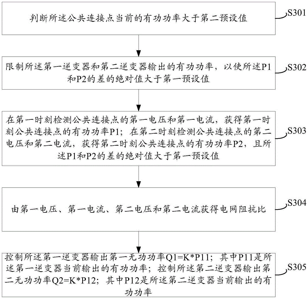
[0086] see image 3 , which is a flow chart of the manual mode of the method for suppressing voltage fluctuations in photovoltaic power plants provided by the present invention.

[0087] It should be noted that suppressing the voltage fluctuation at the PCC point may be performed in a manual mode or in an automatic mode. The specific implementation process of the manual mode is firstly introduced below.

[0088] S301: Judging that the current active power of the common connection point is greater than a second preset value;

[0089] It should be noted that there is no relationship between the first preset value and the second preset value, the first preset value may be greater than the second preset value, or the first preset value may be smaller than the second preset value. For example, in this embodiment, the first preset value is set to 0.1Pn, and the second preset value is set to 0.2Pn. The first preset value and the second preset value can be set according to actual n...


PUM


Abstract

The embodiment of the invention discloses a method and system for inhibiting voltage fluctuation of a photovoltaic power station. The method includes the steps that a first voltage Vp1 and a first current Ip1 of a public coupling point are detected at a first moment, and active power P1 of the public coupling point at the first moment is obtained through the Vp1 and the Ip1; a second voltage Vp2 and a second current Ip2 of the public coupling point are detected at a second moment, active power P2 of the public coupling point at the second moment is obtained through the Vp2 and the Ip2, and the absolute value of the difference of the P1 and the P2 is larger than the first preset value; the grid impedance ratio is obtained through the Vp1, the Ip1, the Vp2 and the Ip2; a first inverter is controlled to output first reactive power Q1, and Q1=K*P11; the P11 is active power currently output by the first inverter; a second inverter is controlled to output second reactive power Q2, and Q2=K*P12; the P12 is active power currently output by the second inverter. The method is simple, the real-time request of communication is not high, and the inverters do not need to be controlled in real time to conduct reactive power adjustment; the reactive power output by the inverters needs to be adjusted only when the grid impedance ratio changes.

Description

technical field [0001] The invention relates to the technical field of inverter control, in particular to a method and system for suppressing voltage fluctuations of a photovoltaic power station. Background technique [0002] With the global energy shortage, photovoltaic power generation is getting more and more attention, see figure 1 , which is a schematic diagram of a photovoltaic power plant system in the prior art. [0003] figure 1 The photovoltaic array substrate is not shown in the figure, and the direct current output by the photovoltaic array substrate is converted into alternating current through the inverter, and fed back to the power grid. [0004] In practical applications, generally multiple inverters are connected in parallel to connect to the grid. like figure 1 As shown, the first inverter 1, the second inverter 2, until the nth inverter N, each inverter is connected to the common connection point (PCC, PointofCommonCoupling) through the corresponding t...

Claims


Application Information

Patent Timeline
IPC IPC(8): H02J3/50H02J3/16
CPCY02E10/56Y02E40/30
Inventor 潘年安陶磊丁杰邹海晏
Owner SUNGROW POWER SUPPLY CO LTD
Why Eureka
Try Eureka