Multilayer capacitor

a multi-layer capacitor and capacitor technology, applied in the field of multi-layer capacitors, can solve the problems of difficulty in setting the esr to a value appropriate for a prescribed esl, and the difficulty of keeping voltage fluctuations within an allowable range to a rapid change of load current, etc., to achieve the effect of suppressing voltage fluctuations in the power sour

Active Publication Date: 2005-12-01
TDK CORPARATION
View PDF9 Cites 13 Cited by
  • Summary
  • Abstract
  • Description
  • Claims
  • Application Information

AI Technical Summary

Benefits of technology

[0009] In view of the foregoing, it is an object of the present invention to provide a multilayer capacitor capable of controlling the ESR value, capable of easily setting an optimal ESR value for a prescribed ESL value, and capable of further suppressing voltage fluctuations in the power source.

Problems solved by technology

Therefore, in the power source for supplying an electric power to the CPU, it is difficult to keeping voltage fluctuations within an allowable range to a rapid change of the load current supplied to the CPU.
However, while conventional multilayer capacitors have been successful in reducing ESL and increasing ESR, they have difficulty setting the ESR to a value appropriate for a prescribed ESL.

Method used


Image

  • Multilayer capacitor
  • Multilayer capacitor
  • Multilayer capacitor

Examples


first embodiment

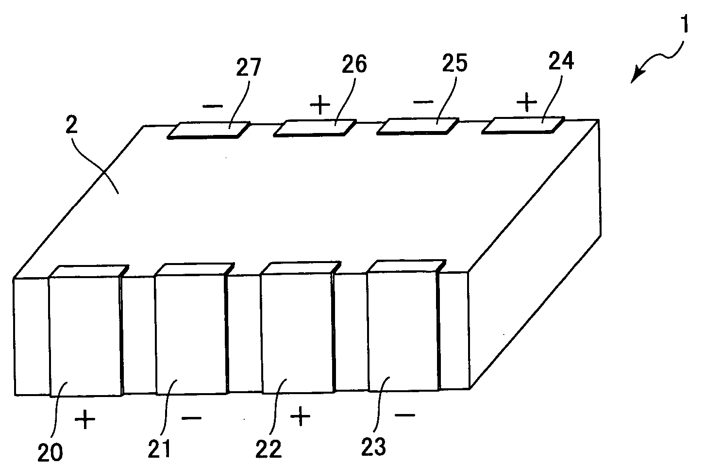
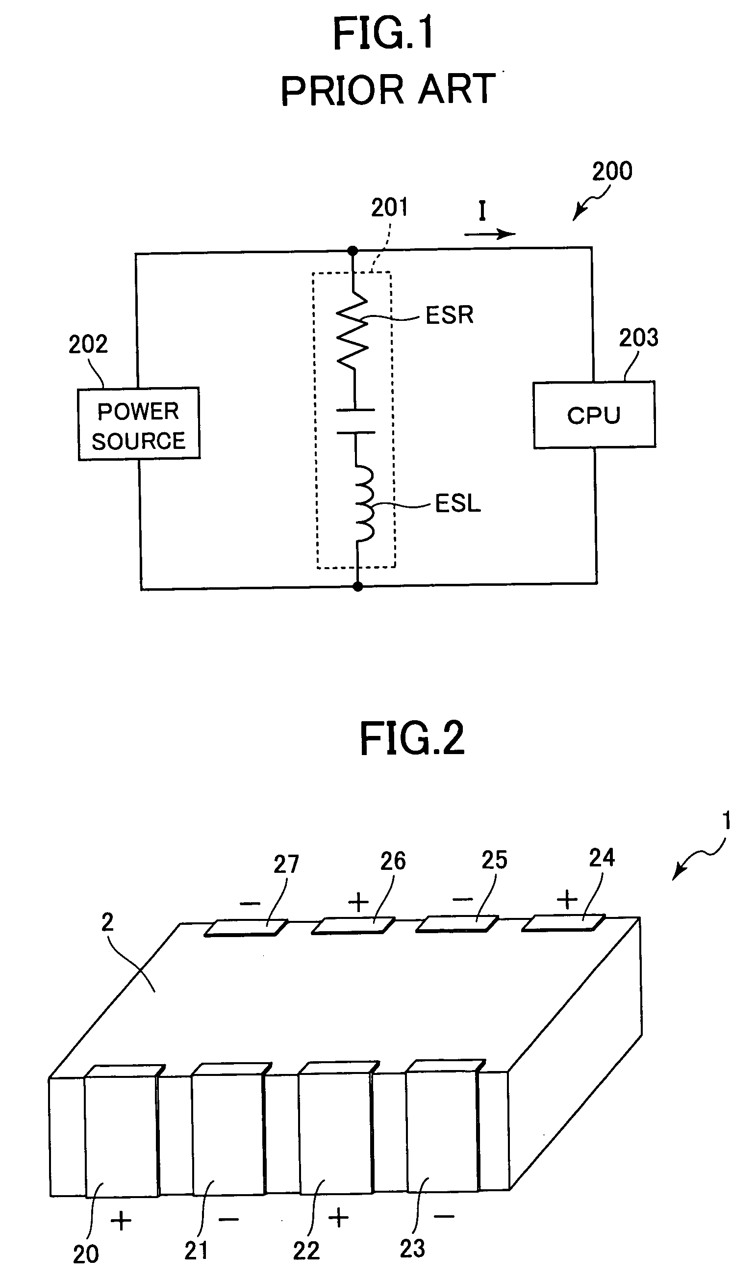
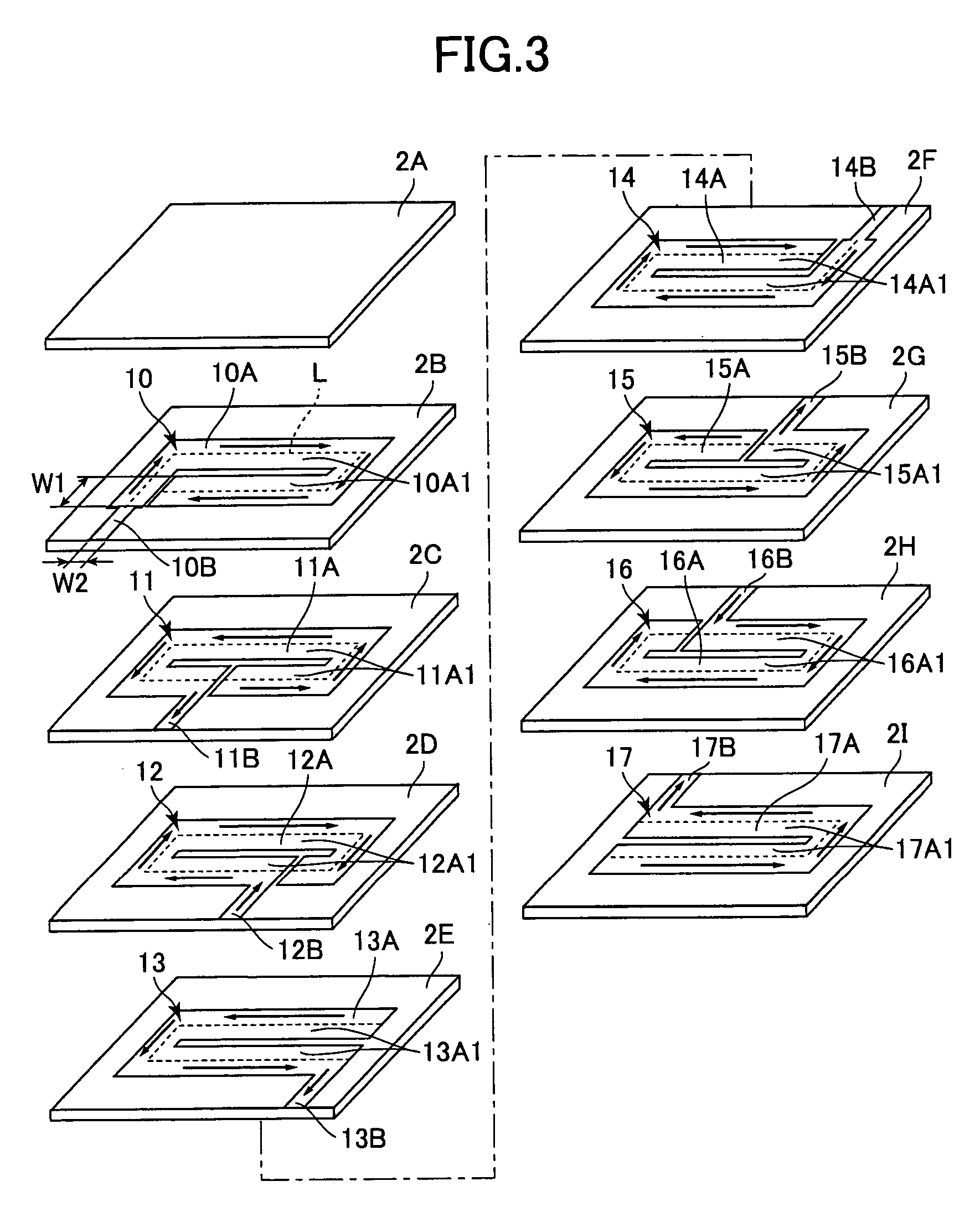
[0020] A multilayer capacitor according to the present invention will be described while referring to FIGS. 2 through 5. As shown in FIGS. 2 and 3, a multilayer capacitor 1 includes a dielectric element 2 formed of stacked sheet-like dielectric layers 2A-2I, first through eighth electrodes 10-17 disposed between adjacent dielectric layers 2A-2I, and eight external electrodes 20-27 connected to the first through eighth electrodes 10-17, respectively.

[0021] The dielectric element 2 is manufactured by sintering the dielectric layers 2A-2I which is ceramic green sheets in a stacked formation. The first through eighth electrodes 10-17 are disposed on each of the dielectric layers 2B-2I, but not on the dielectric layer 2A. The first through eighth electrodes 10-17 are formed of a base metal such as nickel or a nickel alloy, copper or a copper alloy, or a metal alloy having one of these metals as the primary component. The first through eighth electrodes 10-17 are provided with respective ...

second embodiment

[0031] Next, a multilayer capacitor according to the present invention will be described with reference to FIGS. 7 and 8.

[0032] As shown in FIGS. 7 and 8, the multilayer capacitor 101 includes a dielectric element 102 having stacked sheet-like dielectric layers 102A-102E, first through fourth electrodes 110-113 disposed between the dielectric layers 102A-102E, and four external electrodes 120-123 connected to the first through fourth electrodes 110-113, respectively. The dielectric layers 102A-102E correspond to the dielectric layers 2A, 2B, 2E, 2F, and 2I of the first embodiment, and the first through fourth electrodes 110-113 correspond to the first, fourth, fifth, and eighth electrodes 10, 13, 14, and 17 of the first embodiment. Further, the external electrodes 120-123 correspond to the external electrodes 20, 23, 24, and 27 of the first embodiment.

[0033] The dielectric element 102 is manufactured in the same way as the dielectric element 2 according to the first embodiment. Fur...


PUM

PropertyMeasurementUnit
widthaaaaaaaaaa
width W1aaaaaaaaaa
lengthaaaaaaaaaa

Abstract

A multilayer capacitor configured of internal electrodes, each of which has a similar shape that is continuous and has a pair of parallel parts extending parallel to one another. First and second ends of each internal electrode are formed at different positions from those of the other internal electrodes in the stacking direction of the dielectric layers. Each of the internal electrodes has a width W1 that is substantially uniform from the first end to the second end and a length L of a path running through the center of the width W1 from the first to the second end, such that the length L and the width W1 satisfy the expression 8≦L / W1≦33. With this construction, the equivalent series resistance (ESR) of the multilayer capacitor can be maintained within a suitable range, making it possible to obtain a desired value of ESR.

Description

BACKGROUND OF THE INVENTION [0001] 1. Field of the Invention [0002] The present invention relates to a multilayer capacitor, and more particularly to a multilayer capacitor capable of easily acquiring an equivalent series resistance of a desired value. [0003] 2. Description of the Related Art [0004] In recent years, central processing units (CPUs) provided in digital electronic equipment have been moving toward lower voltages and higher load currents. Therefore, in the power source for supplying an electric power to the CPU, it is difficult to keeping voltage fluctuations within an allowable range to a rapid change of the load current supplied to the CPU. [0005]FIG. 1 shows a conventional power circuit 200 for a CPU 203. The power circuit 200 includes a multilayer ceramic capacitor 201 called a decoupling capacitor that is connected to a power source 202. The multilayer capacitor 201 is provided with an equivalent series resistance (ESR) and an equivalent series inductance (ESL). Du...

Claims


Application Information

Patent Timeline
Patent Type & Authority Applications(United States)
IPC IPC(8): H01G4/005H01G4/012H01G4/06H01G4/228H01G4/30H01G4/40
CPCH01G4/012H01G4/40H01G4/30H01G4/12
Inventor TOGASHI, MASAAKI
Owner TDK CORPARATION
Why Eureka
Try Eureka