
Bypath valve

A technology for bypass valves and valve bodies, applied in multi-way valves, valve details, valve devices, etc., can solve the problems of inability to achieve zero leakage, large leakage, and restrictions on the use of bypass valves, and achieve compact structure and sealing performance Good, small size effect

Inactive Publication Date: 2015-06-24
SHANGHAI XINYUE METER FACTORY
View PDF4 Cites 1 Cited by
  • Summary
  • Abstract
  • Description
  • Claims
  • Application Information

AI Technical Summary

Problems solved by technology

[0003] The bypass valve in the prior art adopts gap seal, which cannot achieve zero leakage, and the leakage is relatively large
[0004] In some missile weapons, launch vehicles and other hydraulic systems that have strict leakage requirements and very high reliability requirements, the use of bypass valves in the prior art is limited

Method used


Image

  • Bypath valve

Examples


Embodiment Construction

[0022] The present invention will be further elaborated below by describing a preferred specific embodiment in detail in conjunction with the accompanying drawings.

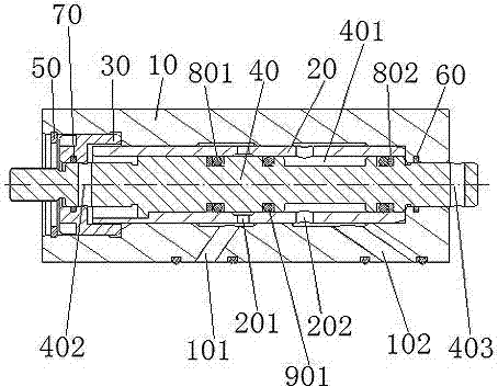
[0023] Such as figure 1 As described, a bypass valve includes: a valve body 10, the valve body 10 includes a through hole arranged along its axial direction and the first oil on the side wall of the valve body 10 respectively connected to the two chambers of the actuator. oil pipeline 101 and the second oil pipeline 102; the bushing 20 is arranged in the through hole of the valve body 10, and is pressed into the valve body 10 by means of interference fit, and the axial length of the bushing 20 is smaller than that of the valve body. The axial length of the body 10, the bushing 20 includes an inner cavity arranged along its axial direction, the bushing 20 is provided with a first oil passage hole 201 and a second oil passage hole 202, corresponding to the valve body 10 The first oil pipeline 101 and the second oi...


PUM


Abstract

The invention discloses a bypath valve which comprises a valve body, a bush, a lock nut and a valve element, wherein the valve body comprises a through hole which is formed in the axial direction of the valve body and a first oil-way pipeline and a second oil-way pipeline which are located on the side wall of the valve body and connected with two cavities of an actuator cylinder respectively; the bush is arranged in the through hole of the valve body and comprises an inner cavity which is formed in the axial direction of the bush, and a first oil-way hole and a second oil-way hole are formed in the bush and correspond to the first oil-way pipeline and the second oil-way pipeline of the valve body respectively; the lock nut is arranged on the end portion of the bush and located in the through hole of the valve body; the valve element passes through the lock nut and the inner cavity of the bush, the two ends of the valve element are located at the outer side of the valve body, the valve element can move relative to the bush, a groove is formed in the valve element in the circumferential direction, and the width of the groove is greater than the distance between the first oil-way hole and the second oil-way hole. The bypath valve has the advantages of being good in sealing property, simple in opening mode, smaller in size, and suitable for being used on a system which is compact in space structure.

Description

technical field [0001] The invention relates to a liquid flow control device, in particular to a bypass valve. Background technique [0002] The bypass valve is a liquid flow control device in the hydraulic system, which is installed between the two chambers of the actuator. When the hydraulic system is working, the bypass valve is closed, and the oil cannot directly communicate with the two chambers of the actuator through the bypass valve; when the hydraulic system is not working, but the piston rod needs to be moved, the bypass valve can be opened to let the actuator The oil in the two chambers of the moving cylinder communicates directly through the bypass valve to push the piston rod to move. [0003] The bypass valve in the prior art adopts gap seal, which cannot achieve zero leakage, and the leakage amount is relatively large. [0004] In some missile weapons, carrier rockets and other hydraulic systems with strict leakage requirements and very high reliability requ...

Claims


Application Information

Patent Timeline
IPC IPC(8): F16K11/07F16K41/02
CPCF16K11/07F16K41/02
Inventor 腾斌峰李旭
Owner SHANGHAI XINYUE METER FACTORY
Learn More