

Public voltage regulating method and device and display device
A technology of common voltage and adjustment method, applied in static indicators, instruments, etc., can solve the problems of poor flicker uniformity, affecting display effect, and small flicker in the center area.
- Summary
- Abstract
- Description
- Claims
- Application Information
AI Technical Summary
Problems solved by technology
Method used
Image

Examples
Embodiment 1
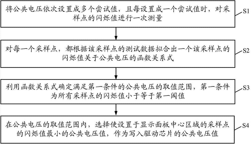
[0067] This embodiment provides a public voltage regulation method, including:
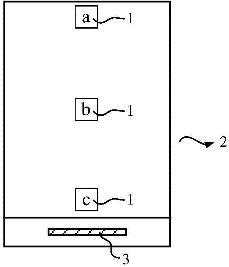
[0068] Step 1, setting sampling points, the sampling points at least include: sampling points set in the center area of the display panel and sampling points set in the edge area of the display panel.
[0069] In the public voltage adjustment method provided in this implementation, the flicker level of the area where the sampling point is located is obtained by measuring the flicker value of the sampling point. One sampling point is set in the center area and the edge area respectively. The more sampling points, the more uniform the distribution on the display panel, and the more consistent the flicker after step 2 common voltage optimization setting, but it also means that the step 2 common voltage optimization setting is more difficult and the amount of calculation is greater, so generally speaking, as long as the flickering It is sufficient to set sampling points in representative areas of...
example 1
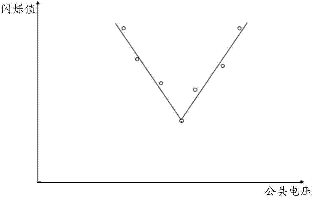
[0113] Example 1, the process of this example is as follows Figure 6 As shown, in this example, the setting of sampling points on the display panel is as follows figure 1 shown. In step S1, test data of sampling points a, b, and c are obtained. In step S2, according to the test data fitting of the sampling point, a piecewise linear function relational expression corresponding to each sampling point is obtained, specifically as Figure 4 As shown, the curves A, B, and C represent respectively figure 1 The functional relationship expressions y1(x), y2(x), y3(x) corresponding to the sampling points a, b, and c in . Step S3 is specifically as follows:
[0114] First, step S31 presets the values P1 and P2 of two flicker values, and P1
[0115] Step S32 For the given value of P1, calculate the solution of the inequality group: y1(x)≤P1, y2(x)≤P1, y3(x)≤P1, if there is a solution, that is, X1≤x≤X2, then this The range is defined as the first value ran...
Embodiment 2
[0124] This embodiment provides a common voltage adjustment device. The common voltage adjustment device is used to optimize the common voltage value written into the drive chip, so that when the display panel is loaded with the common voltage value for display, the flicker value of the sampling point on the display panel All are less than or equal to the first threshold, and the sampling points at least include: sampling points set in the center area of the display panel and sampling points set in the edge area of the display panel.
[0125] The common voltage adjusting device of this embodiment is used to implement the common voltage adjusting method in the first embodiment, optimize the written value of the common voltage of the drive chip, and when the display panel loads the written value of the common voltage optimized by the embodiment of the present invention for display, Not only the flicker in the center area is smaller, but also the flicker in the edge area is ef...
PUM
 Abstract
Description
Claims
Application Information