
A reversible heating tube installation structure and electric oven

A technology of installation structure and heating pipe, which is applied in the direction of roaster/barbecue grill, kitchen utensils, household utensils, etc. It can solve the problems of odor, bacteria breeding, and component damage, so as to improve the service life, facilitate cleaning, and avoid The effect of destruction

Active Publication Date: 2018-10-16
HAIER GRP CORP +1
View PDF5 Cites 0 Cited by
  • Summary
  • Abstract
  • Description
  • Claims
  • Application Information

AI Technical Summary

Problems solved by technology

[0002] The oven is an electrical appliance used to bake food or dry products. The oven will produce grease, smoke and other impurities during the baking process. These impurities will adhere to the inner wall of the oven. If it is not cleaned for a long time, bacteria will grow and in During the baking process, there will be peculiar smell, which will affect the normal use of the oven
[0003] At present, the heating tubes in the oven are all fixed, so the impurities adhering to the side wall with the heating tubes on the inner tank cannot be cleaned well. To completely remove them, the heating tubes need to be disassembled, and the operation is complicated and easily lead to damage to parts

Method used


Image

  • A reversible heating tube installation structure and electric oven
  • A reversible heating tube installation structure and electric oven
  • A reversible heating tube installation structure and electric oven

Examples


Embodiment 1

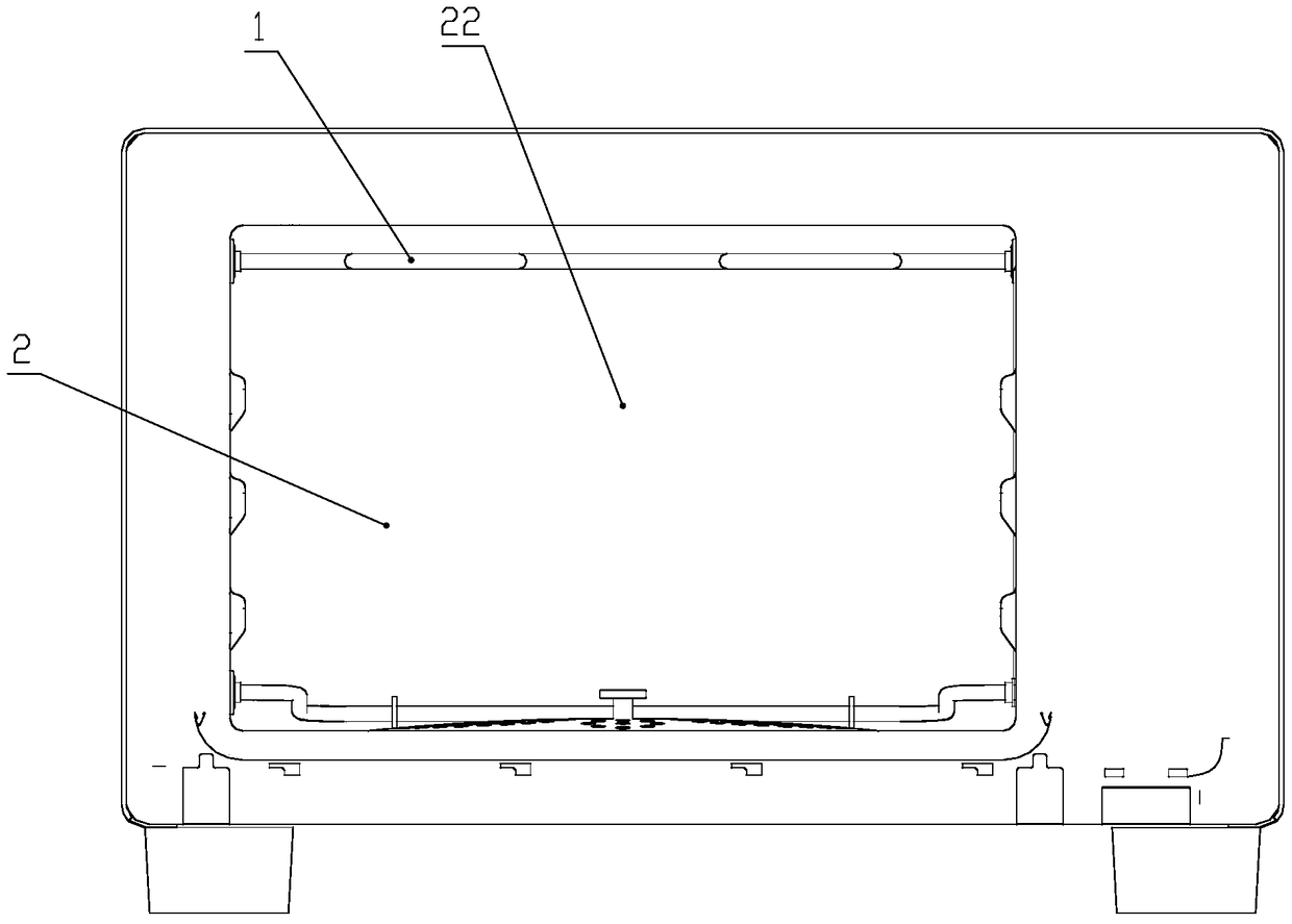
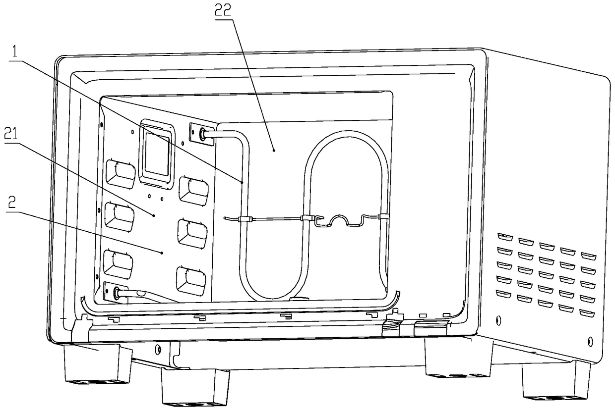
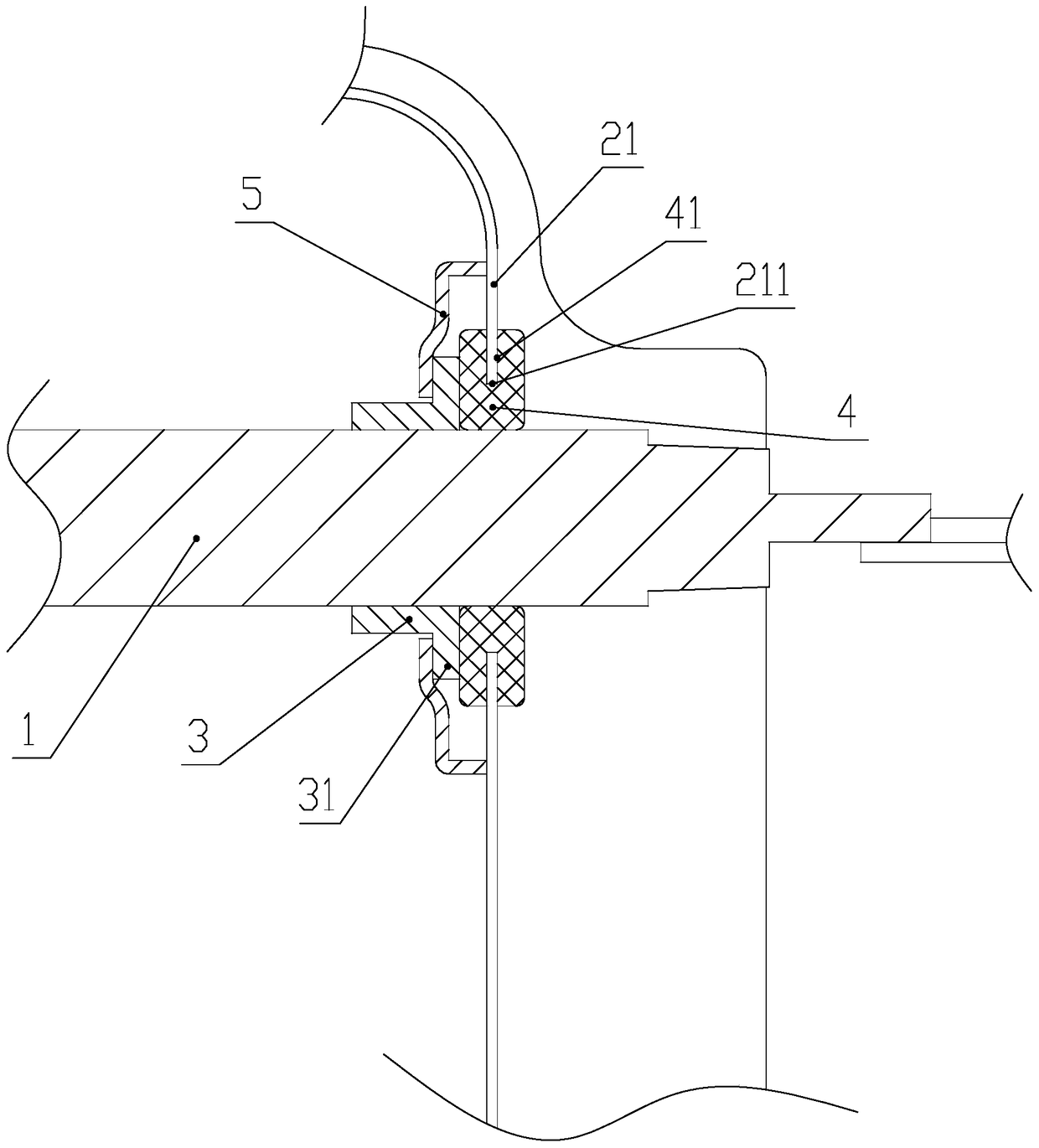
[0034] image 3 It is a schematic diagram of the reversible heating tube installation structure of this embodiment. As shown in the figure, both ends of the heating tube 1 are covered with a shaft sleeve 3, the heating tube 1 is fixedly connected to the shaft sleeve 3 and the two ends of the heating tube 1 are respectively connected to the axis of the shaft sleeve 3 on it. coincide.

[0035] Both side walls 21 of the liner are provided with heating pipe installation holes 211, the two ends of the heating pipe 1 are penetrated in the heating pipe installation holes 211, and there are sealing ring 4. The setting of the sealing ring 4 can provide a certain damping for the rotation of the heating tube 1 on the one hand, and on the other hand can play a role of sealing to avoid the influence of water vapor overflow on the electrical performance of the terminal part. In order to ensure that the sealing ring 4 does not fall off, an installation groove 41 is formed on the outer per...

Embodiment 2

[0039] Figure 4 It is a schematic diagram of the reversible heating tube installation structure of this embodiment. As shown in the figure, the installation structure is basically the same as that of Embodiment 1. Both ends of the heating tube 1 are covered with a rotating shaft sleeve 3, and the heating tube 1 is fixedly connected to the rotating shaft sleeve 3, and the two ends of the heating tube 1 are respectively connected to the sleeve. The axes of the rotating shaft casing 3 on it are coincident. Both side walls 21 of the liner are provided with heating pipe installation holes 211, the two ends of the heating pipe 1 are penetrated in the heating pipe installation holes 211, and there are sealing ring 4. An installation groove 41 is formed on the outer peripheral surface of the seal ring 4 , and the seal ring 4 is clamped and fixed with the side wall 21 of the inner container through the installation groove 41 .

[0040] The difference is that the rotating shaft slee...


PUM


Abstract

The invention discloses a turnable-heating-tube mounting structure and an electric oven and aims to solve the problem that the side walls, on which a heating tube is arranged, of the inner container of a conventional electric oven are hard to clean. The turnable-heating-tube mounting structure comprises a box body and a heating tube mounted in the box body, wherein the box body is provided with a wall surface; the heating tube is mounted close to the wall surface and arranged in the box body in turnable manner; and in the turning state, at least part of the heating tube deviates from the wall surface. The invention also provides the electric oven with the mounting structure. The two ends of the heating tube are rotatably mounted on two side walls of the inner container of the electric oven, and the heating tube can rotate by a preset angle along the axis where the two end parts of the heating tube are positioned, so that the wall surface, on which the heating tube is fixed, of the inner container is exposed outside to be conveniently cleaned.

Description

technical field [0001] The invention relates to a reversible heating tube installation structure and an electric oven. Background technique [0002] The oven is an electrical appliance used to bake food or dry products. The oven will produce grease, smoke and other impurities during the baking process. These impurities will adhere to the inner wall of the oven. If it is not cleaned for a long time, bacteria will grow and in Odors will be generated during the baking process, which will affect the normal use of the oven. [0003] At present, the heating tubes in the oven are all fixed, so the impurities adhering to the side wall with the heating tubes on the inner tank cannot be cleaned well. To completely remove them, the heating tubes need to be disassembled, and the operation is complicated And it is easy to cause damage to parts. Contents of the invention [0004] An object of the present invention is to provide a reversible heating tube installation structure that is ...

Claims


Application Information

Patent Timeline
Patent Type & Authority Patents(China)
IPC IPC(8): A47J37/06
Inventor 徐进礼张朋刘文涛邓鹏飞
Owner HAIER GRP CORP
Learn More