

Earth leakage detection device
A leakage detection and output voltage technology, which is applied to measuring devices, circuit devices, emergency protection circuit devices, etc., can solve problems such as failure to identify leakage
- Summary
- Abstract
- Description
- Claims
- Application Information
AI Technical Summary
Problems solved by technology
Method used
Image

Examples
no. 1 approach
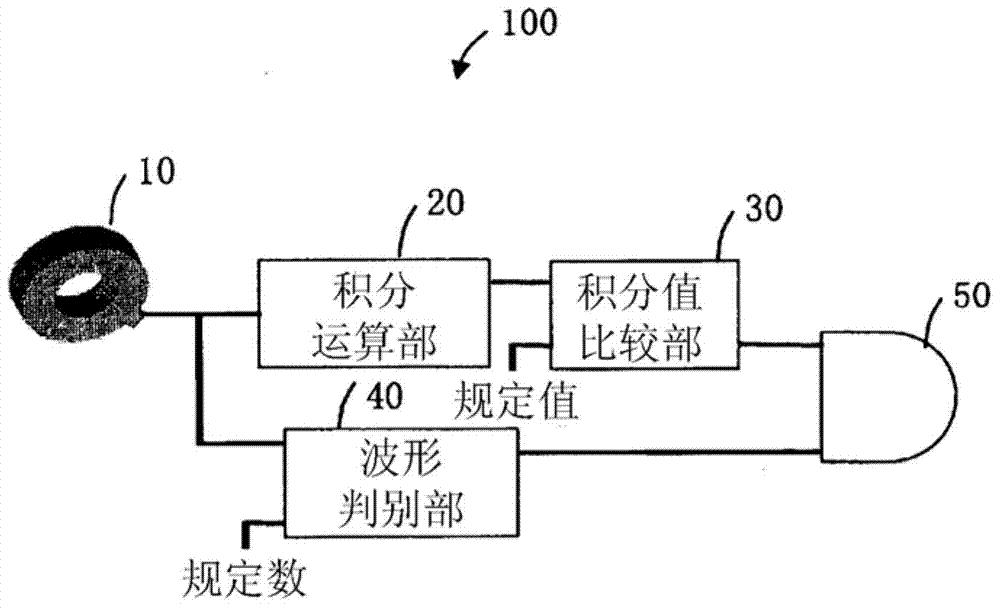
[0105] figure 1 It is a block diagram showing a configuration example of the leakage detection device in the first embodiment of the present invention. figure 1 The shown leakage detection device 100 is configured to include a zero-phase current transformer 10 , an integral calculation unit 20 , an integral value comparison unit 30 , a waveform discrimination unit 40 , and a leakage detection unit 50 .
[0106] The zero-phase converter 10 is composed of an annular iron core (core) and a toroidal coil wound on the core, wherein the iron core is formed of a magnetic body such as a soft magnetic material, and constitutes a three-phase circuit. A plurality of primary conductors of an alternating current circuit pass through the iron core. When a difference occurs between the current flowing in the outward direction and the current flowing in the homeward direction of the AC circuit, a leakage current based on the difference is generated in the zero-phase converter 10 . Further...
no. 2 approach
[0148] Such as Figure 8 As shown, the leakage detection device 100 of the second embodiment includes a waveform discrimination unit 40B instead of the waveform discrimination unit 40 shown in the first embodiment. In addition, the same code|symbol is attached|subjected to the structure of the leakage detection device 100 of this embodiment which is the same as that of the leakage detection device 100 shown in 1st Embodiment, and description is abbreviate|omitted.
[0149] Figure 8 It is a block diagram showing a configuration example of the waveform discrimination unit 40B in the second embodiment of the present invention. Figure 8 The illustrated waveform discrimination unit 40B includes a count value changing unit 43 in addition to the pulse generating unit 41 and the pulse counting unit 42 .
[0150] The count value changing unit 43 is composed of a control circuit and the like, detects the pulse output width based on the pulse generated by the pulse generating unit 41...
no. 3 approach
[0161] The leakage detection device 100 of the third embodiment includes a waveform discrimination unit 40C instead of the waveform discrimination unit 40 shown in the first embodiment. In addition, the components of the leakage detection device 100 of the present embodiment that are the same as those of the leakage detection device 100 shown in the first embodiment are denoted by the same symbols, and description thereof will be omitted.
[0162] Figure 10 It is a block diagram showing a configuration example of the waveform discrimination unit 40C in the third embodiment of the present invention. Figure 10 The illustrated waveform discrimination unit 40C includes a pulse generation condition changing unit 44 in addition to the pulse generation unit 41 and the pulse count unit 42 .
[0163] The pulse generation condition change unit 44 is composed of a control circuit, etc., and changes the pulse generation condition of the pulse generation unit 41 and / or the pulse count c...
PUM
 Abstract
Description
Claims
Application Information