Slider lock assembly and automatic upper rail and lower rail assembly device and assembly method thereof

An automatic assembly and slider lock technology, which is applied in the direction of assembly machines, metal processing equipment, manufacturing tools, etc., can solve the problems of poor fixing effect of slider locks, low degree of automation, and long time-consuming manual assembly, so as to achieve the degree of dependence Reduce and save labor costs and prolong the service life

Active Publication Date: 2015-07-15
苏州泰克诺机电有限公司
View PDF6 Cites 11 Cited by
  • Summary
  • Abstract
  • Description
  • Claims
  • Application Information

AI Technical Summary

Problems solved by technology

[0002] In the manufacturing process of the car seat slide rail, after the upper rail and the lower rail are respectively manufactured, a slider lock needs to be fixed on the upper rail, and then the upper rail and the lower rail are assembled together to form a whole. The prior art The installation of the middle slide lock is often carried out manually by the staff. Manual assembly takes a long time, the assembly efficiency is low, the degree of automation is not high, and the fixing effect of the slide lock is not good; at the same time, the assembly of the upper rail and the lower rail often requires additional work. Production line, which further separates the two processes, so an automated equipment that can automatically install the slider lock and assemble the upper and lower rails is required

Method used


Image

  • Slider lock assembly and automatic upper rail and lower rail assembly device and assembly method thereof
  • Slider lock assembly and automatic upper rail and lower rail assembly device and assembly method thereof
  • Slider lock assembly and automatic upper rail and lower rail assembly device and assembly method thereof

Examples


Embodiment Construction

[0030] Objects, advantages and features of the present invention will be illustrated and explained by the following non-limiting description of preferred embodiments. These embodiments are only typical examples of applying the technical solutions of the present invention, and all technical solutions formed by adopting equivalent replacements or equivalent transformations fall within the protection scope of the present invention.

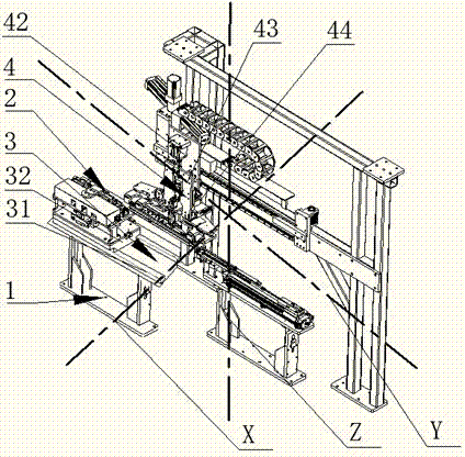
[0031] The present invention discloses a slide lock assembly, upper and lower rail automatic assembly equipment, as attached figure 1 As shown, it includes a base 1 on which a frame is arranged, and also includes a slide lock assembly mechanism 2 , a feeding mechanism 3 and an upper and lower rail assembly mechanism 4 arranged on the base 1 .

[0032] Wherein, the feeding mechanism 3 includes a guide slide rail 31, the guide slide rail 31 is arranged on the base 1 through bolts, and a slide frame 32 is slidably arranged on the guide slide rail 31, th...


PUM


Abstract

The invention discloses a slider lock assembly and automatic upper rail and lower rail assembly device and an assembly method thereof. The slider lock assembly and automatic upper rail and lower rail assembly device comprises a base, and also comprises a slider lock assembly mechanism, a feeding mechanism and an upper rail and lower rail assembly mechanism which are arranged on the base, the feeding mechanism is arranged on the base, the slider lock assembly mechanism is arranged on the feeding mechanism, and the upper rail and lower rail assembly mechanism is arranged at the upper end of the feeding mechanism in a clearance fit manner, and is matched with the slider lock assembly mechanism. By utilizing the inherent structural characteristics and mutual matching relation of an upper rail and a slider lock, by means of an ingenious upward pushing and downward placement structure, the slider lock assembly and automatic upper rail and lower rail assembly device can effectively fasten the slider lock onto the upper rail, thus realizing the automatic mounting of the slider lock; moreover, by sufficiently utilizing the matching between the upper rail structure and a lower rail structure and arranging a plurality of moving structures, the slider lock assembly and automatic upper rail and lower rail assembly device can effectively carry out the automatic assembly of the upper rail and the lower rail, realizes fully automated production, and greatly increases the efficiency of production; furthermore, manpower cost is reduced, and the degree of dependence on workers is decreased greatly.

Description

technical field [0001] The invention relates to an automatic assembly device and an assembly method, in particular to an automatic assembly device for sliding bar locks, upper and lower rails and an assembly method thereof. Background technique [0002] In the manufacturing process of the car seat slide rail, after the upper rail and the lower rail are respectively manufactured, a slider lock needs to be fixed on the upper rail, and then the upper rail and the lower rail are assembled together to form a whole. The prior art The installation of the middle slide lock is often carried out manually by the staff. Manual assembly takes a long time, the assembly efficiency is low, the degree of automation is not high, and the fixing effect of the slide lock is not good; at the same time, the assembly of the upper rail and the lower rail often requires additional work. The production line, which further separates the two processes, requires an automated device that can automatically...

Claims


Application Information

Patent Timeline
Patent Type & Authority Applications(China)
IPC IPC(8): B23P21/00
CPCB23P21/00
Inventor 曹义军
Owner 苏州泰克诺机电有限公司
Why Eureka
Try Eureka