
A stress-free valve body structure

A stress-free, valve body technology, applied in the field of hydraulic accessories, can solve problems such as control valve body deviation

Inactive Publication Date: 2017-12-26
EAST & WEST AVIATION TECH DEV NINGBO
View PDF1 Cites 0 Cited by
  • Summary
  • Abstract
  • Description
  • Claims
  • Application Information

AI Technical Summary

Problems solved by technology

At this time, there will be a large deviation in controlling the flow of the fluid and the opening and closing of the valve body through the spring.

Method used


Image

  • A stress-free valve body structure
  • A stress-free valve body structure
  • A stress-free valve body structure

Examples


Embodiment Construction

[0017] The present invention will be further described in detail below in conjunction with the accompanying drawings and embodiments.

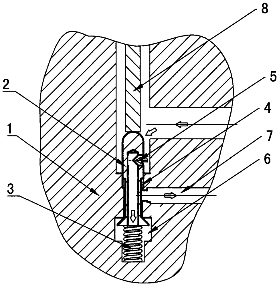
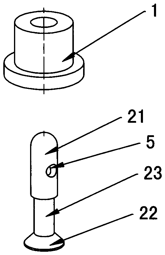
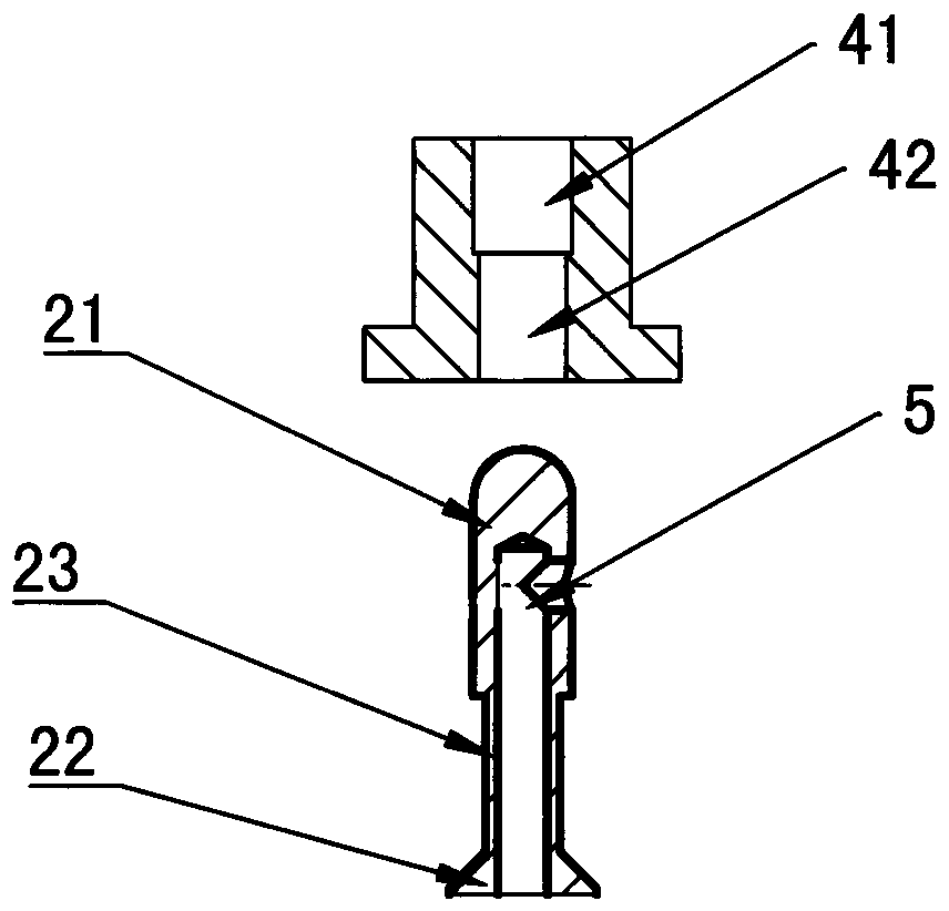
[0018] like Figure 1 to Figure 4 Shown: a stress-free valve body structure, including a valve seat 1 and a valve core 2. The valve seat 1 is provided with a valve port 4 that runs through the upper and lower planes. The valve port 4 includes a cylindrical upper valve port 41 and a lower valve port. 42, the caliber of the upper valve port 41 is greater than the caliber of the lower valve port 42 by a predetermined value, the valve core part 2 is stuck in the valve port 4 and the upper end of the valve core part 2 passes through the upper valve port 41, and the upper end of the valve core part 2 A water inlet 5 is provided, and the water inlet 5 runs through the lower bottom surface of the valve core part 2. The valve core part 2 includes an upper valve core 21 located at the upper end of the upper valve port 41 and a lower valve core 22 locate...


PUM


Abstract

The invention discloses a stress-free valve body structure. The stress-free valve body structure comprises a valve seat and a valve core piece, wherein a valve opening which penetrates through the upper surface and the lower surface is formed in the valve seat, the valve opening comprises a cylindrical upper valve opening and a cylindrical lower valve opening, the aperture of the upper valve opening is greater than the aperture of the lower valve opening by a preset value, the valve core piece is clamped in the valve opening, the upper end of the valve core piece penetrates out of the upper valve opening, a water inlet is formed in the upper end of the valve core piece and penetrates through the lower bottom surface of the valve core piece, the valve core piece comprises an upper valve core which is positioned at the upper end of the upper valve opening and a lower valve core which is positioned at the lower end of the lower valve opening, the upper valve core is adapted to the upper valve opening in structure and is used for sealing the upper end of the upper valve opening, the lower valve core is clamped in an opening in the lower end of the lower valve opening and is used for sealing the opening in the lower end of the lower valve opening, the upper valve core and the lower valve core are connected through a connecting core, a groove is formed in the lower part of the valve core piece, and a water outlet is formed in the middle part of the valve seat. According to the stress-free valve body structure disclosed by the invention, self pressing is realized under the situation of having no the action of a spring, i.e., the opening and the closing of the valve opening cannot be affected by long-time use.

Description

technical field [0001] The invention relates to a hydraulic fitting, in particular to a stress-free valve body structure. Background technique [0002] A valve is a device that uses a movable part to open, close, or partially block an opening or passage, so that fluid can flow out, be blocked, or be regulated. The hydraulic valve in the prior art uses a steel ball or a metal cone slide valve as the valve core to contact and compress the orifice of the metal valve seat under the action of a spring and fluid pressure. When working, the fluid from the liquid channel in front of the valve body pushes the valve core away under the action of pressure and flows out of the valve body. When the pressure is lost or the directional pressure is applied, the valve core resets and the valve body closes. [0003] The life of the spring is limited, and the frequent compression of the spring or the spring being in a compressed state for a long time will affect the service life of the sprin...

Claims


Application Information

Patent Timeline
Patent Type & Authority Patents(China)
IPC IPC(8): F16K1/36F16K27/02
CPCF16K1/36F16K27/02
Inventor 牛玉春鲍柯序
Owner EAST & WEST AVIATION TECH DEV NINGBO
Learn More