
User access cable connection assembly device and method of use thereof

A technology for connecting components and cables, applied in the field of low-voltage power distribution devices of power supply systems, can solve the problems of improper winding, loose crimping, and non-standard stubble connection of household line cables, so as to improve connection reliability and reduce The effect of bending, the effect of reducing the difference

Active Publication Date: 2017-02-22
STATE GRID SHANDONG ELECTRIC POWER +1
View PDF5 Cites 0 Cited by
  • Summary
  • Abstract
  • Description
  • Claims
  • Application Information

AI Technical Summary

Problems solved by technology

In view of the strict connection requirements, affected by external factors such as climate, temperature, lighting, and fault handling time in actual operation, it is very easy for the connection of the household cable to be untrue, non-standard splicing, and crimping not tight, etc. question

Method used


Image

  • User access cable connection assembly device and method of use thereof
  • User access cable connection assembly device and method of use thereof
  • User access cable connection assembly device and method of use thereof

Examples


Embodiment approach 1

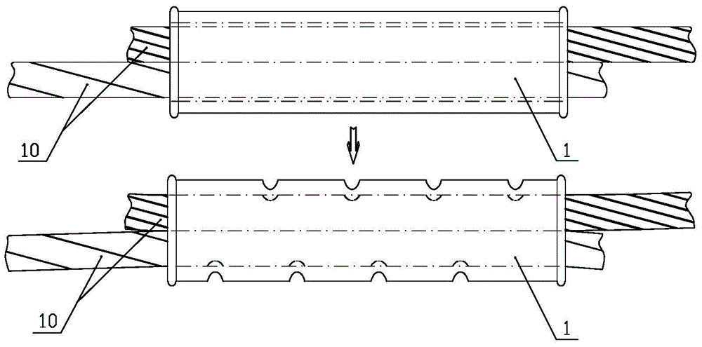
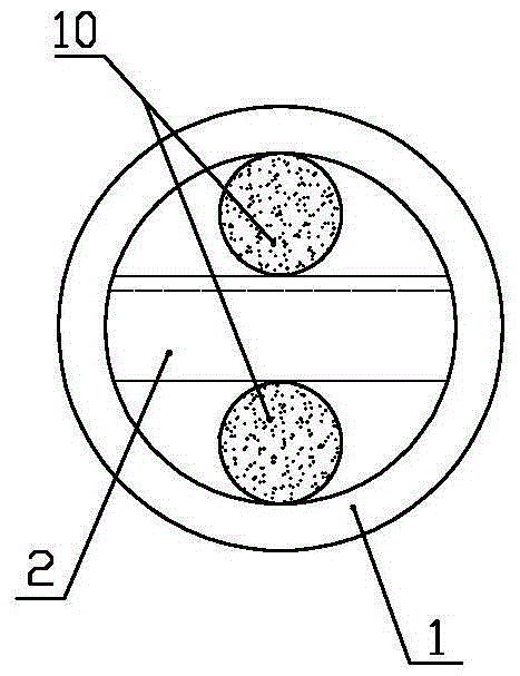
[0058] Such as figure 2 , Figure 5 to Figure 7 The shown user cable connection assembly device includes a sleeve 1 made of copper material and two bayonet pins 2 made of aluminum material, and an insulating layer is provided on the outer wall of the sleeve 1 .

[0059] Such as figure 2 and Figure 7 Shown is a schematic structural view of the bayonet pin 2, the bayonet pin 2 shown in the figure is a bar-shaped body, and its upper end surface is a slope that gradually decreases from left to right and the highest end of the slope ( Figure 7 There is a certain distance from the left end surface, so that the upper end surface of bayonet pin 2 forms a stepped surface. At the center of the lower end plane of the detent 2 (ie Figure 7 The center of the straight line along the front-to-back direction) is provided with an arc-shaped groove 21 extending along its length direction (left-right direction), and the radius of curvature of the arc-shaped groove 21 is equal to the rad...

Embodiment approach 2

[0068] On the basis of Embodiment 1, this embodiment adds two positioning rings and two positioning plugs, by fixing the positioning rings 3 on both ends of the casing 1 and fixing the positioning plugs 4 in the positioning rings 3, at the same time Let the inner end plane of the positioning plug 4 contact the left end face and the right end face of the bayonet pin 2 to limit the axial position of the bayonet pin 2 and prevent the bayonet pin 2 from being axially outward due to excessive assembly or machining errors during application. shift phenomenon, further improving the reliability of the cable 10 connection.

[0069] Such as Figure 9 , Figure 10 , Figure 13 As shown, the shape of the positioning plug 4 is consistent with the annular cavity of the positioning ring 3 . The two positioning rings 3 are respectively fixedly connected to the two ends of the sleeve 1 through existing connection methods such as welding, the ring cavity of the positioning ring 3 communicate...


PUM


Abstract

The invention relates to a service cable connecting assembly apparatus and a usage method thereof. The apparatus comprises a sleeve and block pins, the upper end surface of each block pin is an inclined plane, the lower plane is provided with an arc groove extending in the length direction, the radius of curvature of the arc groove is no less than the radius of a cable, an end surface of one end of the block pin is provided with an axial threaded hole, the axial length of the inclined plane portion of the upper end surface of the block pin is no less than the axial length of the sleeve, the maximum internal diameter of the sleeve is greater than or equal to twice of the sum of the height of the axial central position of the inclined plane portion of the upper end surface of the block pin and the diameter of the cable, an end surface of one end of the block pin, corresponding to the lowest end of the inclined plane of the upper end surface, penetrates through a cavity of the sleeve face to face, the arc grooves at the lower end surfaces of the block pins are respectively matched with an outer wall of the cable, the inclined planes of the two block pins are finally in contact fit, the block pins are made of aluminum materials, the sleeve is made of copper materials, and an outer wall of the sleeve is provided with an insulating layer. According to the apparatus and the usage method thereof, the assembling is convenient, the connection is firm, the deformation of the cable is small, and the reliability and stability of the power transmission performance of a cable connecting position can be guaranteed.

Description

technical field [0001] The invention relates to the field of low-voltage power distribution devices in power supply systems, in particular to a component device for connecting low-voltage household wires and cables. Background technique [0002] Low-voltage power distribution lines are mainly used to directly distribute electric energy to electrical equipment. The lines mainly realize the connection of 10kV transformers, box-type transformers and low-voltage user electrical equipment to complete power distribution. Generally speaking, the household line refers to a section of line between the overhead distribution line and the first support point in the user support. The low-voltage household line refers to a section of line from the low-voltage power line of 0.4kV and below to the first support of the user. In the 380V / 220V low-voltage power distribution system, the electric energy metering device box installed in the residential area is the final equipment for realizing e...

Claims


Application Information

Patent Timeline
Patent Type & Authority Patents(China)
IPC IPC(8): H01R4/60H01R11/03
Inventor 刘勇宋冬梅战祥真孙钰彭
Owner STATE GRID SHANDONG ELECTRIC POWER
Learn More