Electric tool and switch mechanism thereof

A technology for electric tools and switch mechanisms, applied in electric switches, manufacturing tools, circuits, etc., can solve problems such as increasing the cost of electric tools, and achieve the effects of improving safety and reducing fatigue.

Inactive Publication Date: 2015-07-15
BOSCH POWER TOOLS CHINA
View PDF7 Cites 3 Cited by
  • Summary
  • Abstract
  • Description
  • Claims
  • Application Information

AI Technical Summary

Problems solved by technology

However, this will significantly increase the cost of the power tool

Method used


Image

  • Electric tool and switch mechanism thereof
  • Electric tool and switch mechanism thereof
  • Electric tool and switch mechanism thereof

Examples


Embodiment Construction

[0040] The preferred embodiments of the present invention will be described in detail below with reference to examples. Those skilled in the art should understand that these exemplary embodiments do not imply any limitation to the present invention.

[0041] In this application, it refers to the front and rear positions or directions, wherein "front" means close to the "knife" end of the power tool, and rear means close to the opposite end.

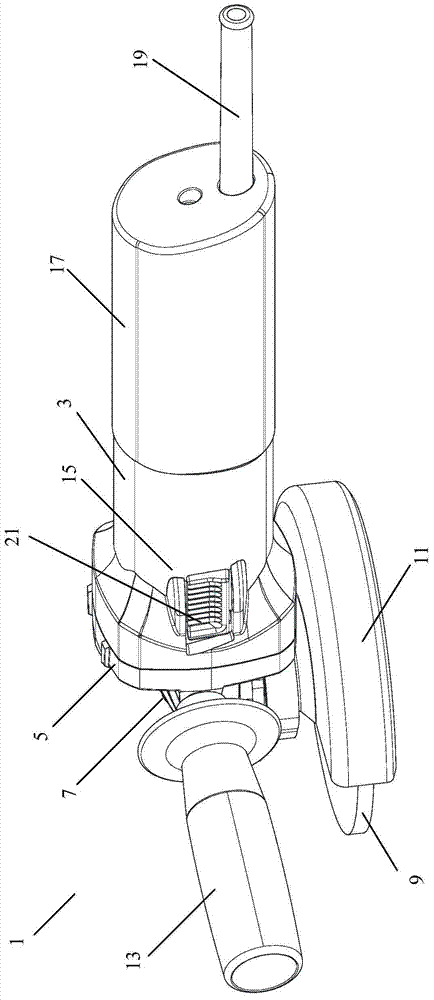
[0042] figure 1 is a perspective view of a power tool having a switch mechanism according to a preferred embodiment of the present invention. Although in figure 1 The power tool 1 is shown as a grinder, but it is understood that it could be any other power tool, such as a chainsaw. Such as figure 1 As shown, the grinder includes a motor housing 3, a motor installed in the motor housing 3, a gear housing 5 positioned at the front end of the motor housing 3, a transmission mechanism 7 partially located in the gear housing 5, and a trans...


PUM


Abstract

The invention relates to a switch mechanism of an electric tool. The switch mechanism is arranged on a motor housing of the electric tool, and comprises a switch button, a sliding bar and a stop mechanism used for preventing the sliding bar from moving to the rear end of the motor housing, wherein the sliding bar is slidingly arranged in an inner side channel arranged on the motor housing, so that the sliding bar can be contacted with a trigger switch on a power supply line; the sliding bar tends to move to the rear end of the motor housing under the action of an elastic force to release pressing on the trigger switch; the switch button is mounted at the front end of the sliding bar in a pivoted manner; an elastic device is arranged between the switch button and the front end of the slender sliding bar; and the elastic device tends to allow the switch button to pivot around a longitudinal axis of the motor housing, so that one side part of the switch button is far away from the motor housing and the other side part of the switch button pushes against the motor housing. The invention further relates to the electric tool comprising the switch mechanism. According to the switch mechanism and the electric tool, a fatigue feeling of an operator can be alleviated, and the safety of the electric tool can be improved.

Description

technical field [0001] The present invention relates to electric tools, in particular to a switch mechanism of the electric tool and an electric tool including such a switch mechanism. Background technique [0002] When an electric tool such as a grinder is in use, the electric tool is energized and operated by pushing the switch button of the switch mechanism. According to different usage requirements of the electric tool, a switch mechanism without a locking function or a switching mechanism with a locking function can be provided for the electric tool. Since the switch mechanism without locking function requires the operator to press the switch button all the time, it is easy to cause operator fatigue. In the existing switch mechanism with locking function, when the electric tool needs to be powered off, the locking mechanism must be manually operated to release the locking, which prevents the electric tool from being powered off immediately as required. Furthermore, if...

Claims


Application Information

Patent Timeline
Patent Type & Authority Applications(China)
IPC IPC(8): H01H13/14B25F5/00
CPCB24B47/26B24B23/028B25F5/02
Inventor 吕卫卫
Owner BOSCH POWER TOOLS CHINA
Why Eureka
Try Eureka