A safety device for preventing side impact vehicle door from opening
A safety device and door opening technology, which is applied in the field of auto parts, can solve the problems of opening, downward movement, deformation, etc., and achieve the effects of good safety performance, high transmission precision, and high transmission precision
- Summary
- Abstract
- Description
- Claims
- Application Information
AI Technical Summary
Problems solved by technology
Method used
Image
Examples
Embodiment 1
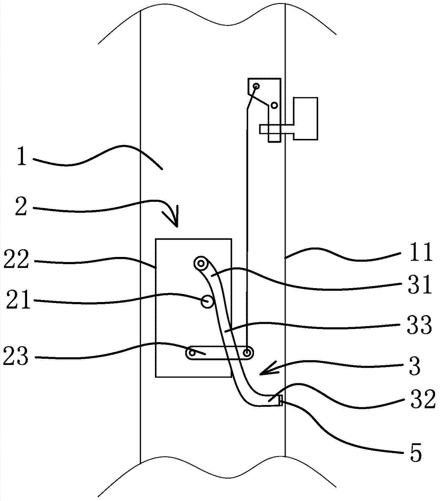
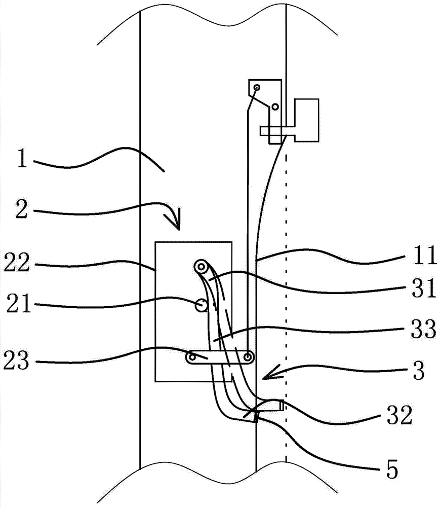
[0027] Such as figure 1 As shown, the automobile includes a car door 1, and a car lock 2 is arranged in the car door 1. The car lock 2 includes an inner locking twist 21 and a lock body 22. The contact part 32 at the outer end and the connecting part 33 in the middle, the hinge part 31 and the connecting part 33 have a smooth transition, the contact part 32 and the connecting part 33 have a smooth transition, the hinge part 31 is hinged with the lock body 22, and the deformation sensing rod 3 can go around the hinge point Rotation, in the present embodiment, there is a gap between the connection of the hinged part 31 and the connecting part 33 and the outside of the inner locking knob 21, and the distance of the gap is 1 mm. In actual production, the distance of the gap can be 5 mm or 10 mm, the joint between the hinged part 31 and the connecting part 33 may also directly abut against the outer side of the inner locking knob 21 . In this embodiment, there is a gap between the...
Embodiment 2
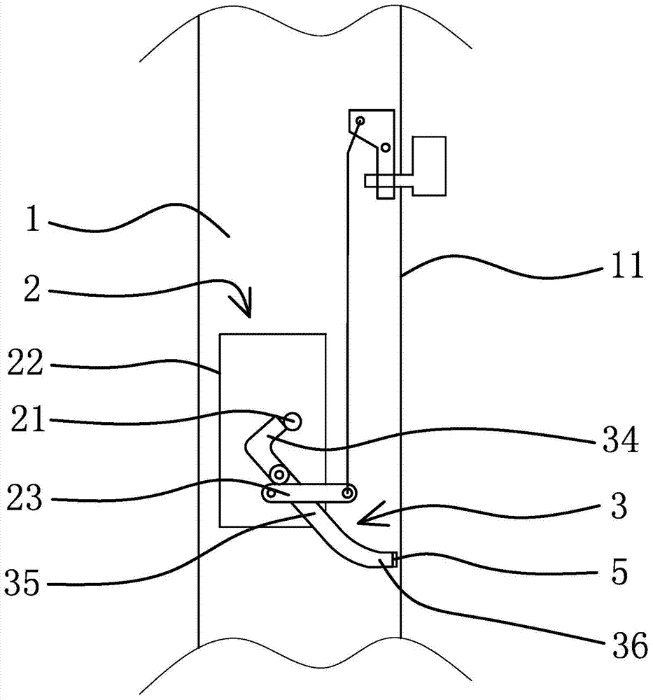
[0030] Such as image 3 As shown, the structure and principle of this embodiment are basically the same as that of Embodiment 1, the difference is that in this embodiment, the deformation sensing rod 3 includes the abutting portion 34 at the inner end, the rotating portion 35 in the middle and the touching portion at the outer end 36, the rotating part 35 and the touch part 36 transition smoothly, the abutting part 34 and the rotating part 35 are approximately perpendicular, the rotating part 35 is hinged with the lock body 22, the deformation sensing rod 3 can rotate around the hinge point, the abutting part 34 and the inner There is a gap between the inner sides of the locking knobs 21, and the distance of the gap is 1mm. In actual production, the distance of the gap can be 5mm or 10mm, and the abutting portion 34 can also abut against the inner side of the inner locking knobs 21, The axial centerline of the touch portion 36 is substantially perpendicular to the outer panel ...
Embodiment 3
[0032] Such as Figure 4 As shown, the structure and principle of this embodiment are basically the same as that of Embodiment 1, the difference is that in this embodiment, the deformation sensing rod 3 is in the shape of a straight rod, and the inner end of the deformation sensing rod 3 is connected to the inner locking torque 21. There is a gap between the outer sides, and the distance of the gap is 1 mm. In actual production, the distance of the gap can be 5 mm or 10 mm. The inner end of the deformation sensing rod 3 can also directly abut against the outer side of the inner locking torque 21, deforming The sensing rod 3 can move along the axial direction of the deformation sensing rod 3 .
PUM
 Abstract
Description
Claims
Application Information
 - R&D
- Intellectual Property
- Life Sciences
- Materials
- Tech Scout
- Unparalleled Data Quality
- Higher Quality Content
- 60% Fewer Hallucinations
Browse by: Latest US Patents, China's latest patents, Technical Efficacy Thesaurus, Application Domain, Technology Topic, Popular Technical Reports.
© 2025 PatSnap. All rights reserved.Legal|Privacy policy|Modern Slavery Act Transparency Statement|Sitemap|About US| Contact US: help@patsnap.com


