
A pmt voltage divider circuit with adjustable magnification

A technology of magnification and voltage divider circuit, which is applied in the direction of dynode circuit layout and electron multiplier detailed information, etc. It can solve problems affecting transit time, PMT magnification, voltage change, etc., and achieve fast recovery time and stable gain , the effect of simple structure

Active Publication Date: 2017-07-04
SHANGHAI UNITED IMAGING HEALTHCARE
View PDF5 Cites 0 Cited by
  • Summary
  • Abstract
  • Description
  • Claims
  • Application Information

AI Technical Summary

Problems solved by technology

Its disadvantage is that when the charge output by the PMT becomes larger, there will be a large current on the voltage dividing resistors of the last few stages of the PMT, which will cause the voltage on the dynode to change, thereby affecting the output of the PMT magnification. stability
[0005] Neither of the above two voltage dividers has the function of adjusting the PMT magnification. To adjust the PMT magnification, the only way to adjust the PMT magnification is to adjust the voltage value of -HV. However, the smaller voltage value not only affects the PMT magnification, but also affects Parameters such as transit time make the performance of PMT worse

Method used


Image

  • A pmt voltage divider circuit with adjustable magnification
  • A pmt voltage divider circuit with adjustable magnification
  • A pmt voltage divider circuit with adjustable magnification

Examples


Embodiment Construction

[0016] The present invention will be further described below in conjunction with the accompanying drawings and embodiments.

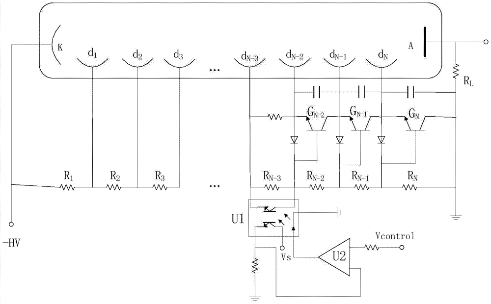
[0017] image 3 It is a structural schematic diagram of the adjustable magnification PMT voltage divider circuit of the present invention.

[0018] See image 3 , the magnification-adjustable PMT voltage divider circuit provided by the present invention includes a photomultiplier tube with multi-stage dynodes, and an RC bias circuit is connected to each stage dynode, and the RC bias circuit includes parallel voltage divider resistors and capacitors, and the voltage dividing resistors between two adjacent dynodes are connected in series in sequence, wherein at least one dynode is provided with a photocoupler, and the output terminal of the photocoupler is connected in parallel to the dynode of this stage On the voltage dividing resistor, the input terminal of the photocoupler is connected with the output terminal of the operational amplifier.

[0019]...


PUM


Abstract

The invention discloses a PMT voltage divider circuit with adjustable magnification. piezoresistors and capacitors, and the voltage dividing resistors between adjacent two stages of dynodes are connected in series in sequence, wherein at least one stage of dynodes is provided with a photocoupler, and the output end of the photocoupler is connected in parallel with the stage dynodes. The input terminal of the optocoupler is connected to the output terminal of the operational amplifier. The adjustable magnification PMT voltage divider circuit provided by the present invention can adjust the gain of PMT conveniently and flexibly by setting a photocoupler at a certain stage of the dynode and using an operational amplifier to control the current output of the photocoupler, and has a simple structure. , has the characteristics of stable gain, low power consumption and fast recovery time.

Description

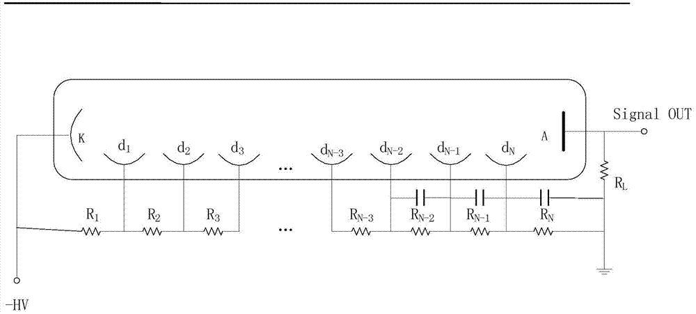
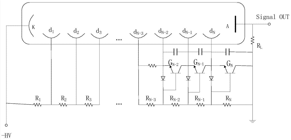
technical field [0001] The invention relates to a voltage dividing circuit, in particular to a PMT voltage dividing circuit with adjustable magnification. Background technique [0002] The voltage divider circuit of the photomultiplier tube (PMT) currently used mainly includes a resistor network, a classic RC bias circuit, and an improved active configuration circuit (including active components of a triode) on the classic RC bias circuit, but There is no voltage divider circuit that can adjust the PMT gain. [0003] The RC voltage divider circuit is a classic PMT voltage divider circuit, the circuit diagram is as follows figure 1 shown. Its disadvantage is that when the charge output by the PMT becomes larger, there will be a large current on the voltage dividing resistors of the last few stages of the PMT, which will cause the voltage on the dynode to change, thereby affecting the output of the PMT magnification. stability. Therefore, it is only suitable for use in det...

Claims


Application Information

Patent Timeline
Patent Type & Authority Patents(China)
IPC IPC(8): H01J43/30
Inventor 王玉凯王超
Owner SHANGHAI UNITED IMAGING HEALTHCARE
Learn More