air conditioning method

A technology for air conditioning and air-conditioning rooms, applied in the field of air-conditioning air supply, can solve problems such as temperature deviation, cooling, heating effect delay, uneven heating and cooling, etc., to increase the direction of air outlet, improve comfort experience, and quickly cool or cool hot effect

Active Publication Date: 2019-03-01
HAIER GRP CORP +1
View PDF5 Cites 0 Cited by
  • Summary
  • Abstract
  • Description
  • Claims
  • Application Information

AI Technical Summary

Problems solved by technology

[0004] However, this air supply device cannot adjust the wind direction during use, so that the air conditioner cannot evenly blow cold or hot air to all angles of the room, resulting in deviations in temperature between the central area where the air outlet of the air conditioner is facing and other surrounding areas, and the entire room is cold. uneven heat
At the same time, the wind sent by the air conditioner tends to gather towards the central area. Therefore, if the user is in the central area, he will feel uncomfortable due to being blown directly by the wind, while other areas outside the central area will feel uncomfortable. There is a delay in cooling and heating effects

Method used


Image

  • air conditioning method
  • air conditioning method
  • air conditioning method

Examples


Embodiment Construction

[0025] The technical solutions of the present invention will be further described in detail below in conjunction with the accompanying drawings and specific embodiments.

[0026] First of all, a brief description of the technical terms involved in this specific embodiment: when referring to the front or back of each structural component, it is defined by the position of the structural component relative to the user under normal use ; When describing the arrangement position of multiple structural parts before or after, it is also the definition of the position of the device composed of multiple structural parts relative to the user in the normal use state.

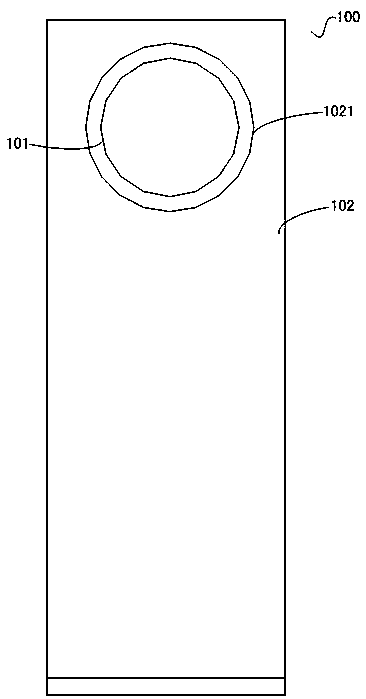
[0027] See figure 1 , which shows a front view of an embodiment of an air conditioner applying the air supply method of the present invention.

[0028] Such as figure 1 As shown, the air conditioner of this embodiment includes an indoor unit body 100, the indoor unit body 100 has a front panel 102, and an air outlet 1021...


PUM


Abstract

The invention discloses an air supplying method of an air conditioner. The method is that an air supplying device of the air conditioner is arranged in an indoor unit body of the air conditioner, wherein the air supplying device of the air conditioner comprises an air supply body; the air supply body comprises at least three air guide bodies of which the middle parts can be communicated, and openings are formed in the front and back of each air guide body; the air guide bodies are arranged from front to back in a sequence, and a through air channel of which the front and the back are communicated is formed between the air guide bodies; an air supply gap is formed between two adjacent air guide bodies. The method is characterized in that the air supply gaps between the adjacent front air guide body, the medium air guide body and the rear air guide body of the air guide bodies which are sequentially arranged from front to back are dynamically changed during supplying air, thus the air supply quantity of the air supply gaps in different directions can be changed, and as a result, the air discharging direction of the air supplying device can be changed. With the adoption of the method, the air discharging direction can be adjusted by controlling the air supplying device of the air conditioner, so that the whole indoor area can be uniformly and quickly refrigerated or heated; in addition, the air discharging direction can be adjusted as the user requirement, so that the comfort experience of a user using the air conditioner can be improved.

Description

technical field [0001] The invention belongs to the technical field of air conditioning, and in particular relates to an air-conditioning air supply method. Background technique [0002] At present, when the common vertical air conditioners on the market are blowing air, the air after heat exchange by the heat exchanger is directly blown out from the air outlet provided on the air conditioner under the action of the internal fan, and all the air blown out is heat exchange air. Generally, no additional air supply device is provided between the heat exchanger and the air outlet. One disadvantage of this kind of air supply air is that all the air sent out is heat exchange air, the air volume is limited, and the indoor air circulation speed is slow; another disadvantage is that the air sent out is not soft enough, especially in the cooling mode, the cool air blown directly When it blows on the user, the user feels uncomfortable. [0003] In order to solve this problem, the app...

Claims


Application Information

Patent Timeline
Patent Type & Authority Patents(China)
IPC IPC(8): F24F13/14
CPCF24F13/1413F24F13/1426F24F2013/1433
Inventor 矫立涛刘伟杰雷永锋李大森赵若尘常利华金锦花
Owner HAIER GRP CORP
Why Eureka
Try Eureka