Plug connector and electric connector combination

A technology for plug connectors and electrical connectors, which is applied in the direction of connection, parts and circuits of connecting devices, etc., can solve the problems of wrongly inserting power terminals into an insulating body, and the terminal assembly end is not provided with a foolproof structure, etc., and achieves a foolproof effect. Good results

Active Publication Date: 2015-07-29
立全科技(太仓)有限公司
View PDF4 Cites 5 Cited by
  • Summary
  • Abstract
  • Description
  • Claims
  • Application Information

AI Technical Summary

Problems solved by technology

[0003] However, the existing power connector does not have a fool-proof structure at the terminal assembly end, so it is easier to insert the power terminal into the insulating body by mistake when assembling the power connector

Method used


Image

  • Plug connector and electric connector combination
  • Plug connector and electric connector combination
  • Plug connector and electric connector combination

Examples


Embodiment Construction

[0045] In order to make the object, technical solution and advantages of the present invention clearer, the present invention will be described in detail below in conjunction with the accompanying drawings and specific embodiments.

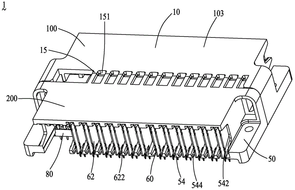
[0046] see figure 1 As shown, the present invention discloses an electrical connector assembly 1 , including a plug connector 100 and a socket connector 200 that are mounted on a circuit board (not shown) and mated with each other.

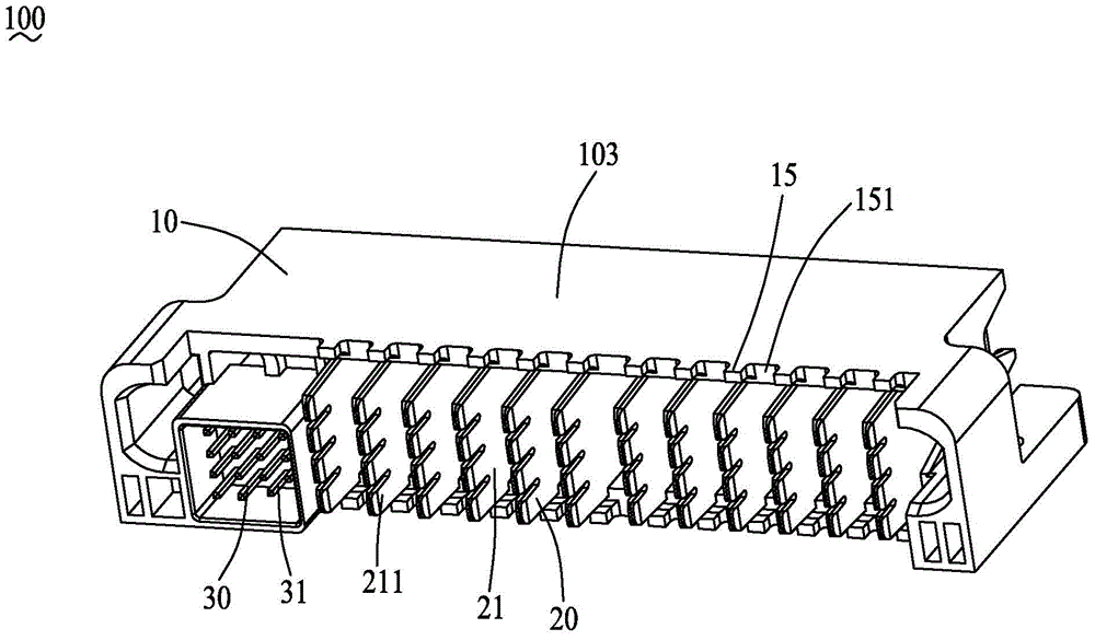
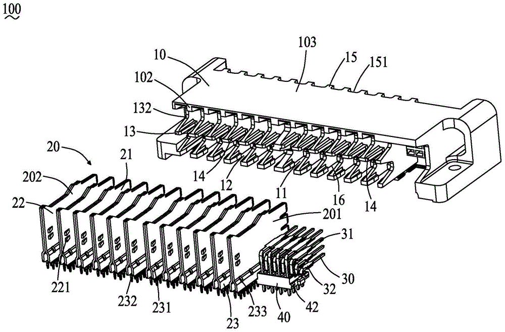
[0047] see figure 2 and image 3 As shown, the plug connector 100 includes an insulating body 10, a plurality of male power terminals 20 and a plurality of male signal terminals 30 accommodated in the insulating body 10, and a plurality of male signal terminals 30 for limiting the position. The first limit block 40. The plurality of male power terminals 20 include a first terminal 201 and a second terminal 202 .

[0048] see Figure 4 to Figure 7 As shown, the insulating body 10 is formed with a mating surface 1...


PUM


Abstract

The invention provides a plug connector and an electric connector combination. The plug connector comprises an insulating body and a plurality of male power terminals; a plurality of first terminal accommodating channels and a plurality of second terminal accommodating channels for accommodating the plurality of male power terminals are formed in the insulating body; every male power terminal is composed of a contact unit, a terminal tail unit and a fixing unit connecting the contact unit and the terminal tail unit; the insides of both the first terminal accommodating channels and the second terminal accommodating channels are provided with terminal clamping units; the fixing unit of every male power terminal is matched with the corresponding terminal clamping unit to fix the male power terminal into the corresponding terminal accommodating channel; the terminal clamping units of the first terminal accommodating channels and the terminal clamping units of the second terminal accommodating channels are arranged in a vertically staggered mode in the height direction of the plug connector.

Description

technical field [0001] The invention relates to an electrical connector, in particular to a plug connector installed on a circuit board and an electrical connector combination with the plug connector. Background technique [0002] With the rapid development of electronic technology, electronic products are becoming more and more high-end and intelligent, and the requirements for power connectors are also getting higher and higher. Existing power connectors generally include an insulating body and a plurality of power terminals assembled in the insulating body. A through hole is provided in the insulating body, and the power terminal is assembled in the hole, so as to facilitate the power conduction between the power connector and the docking connector. Conventional power connectors usually have a fool-proof structure at the butt end to avoid mis-mating with the butt connector. [0003] However, the existing power connector does not have a fool-proof structure at the termin...

Claims


Application Information

Patent Timeline
Patent Type & Authority Applications(China)
IPC IPC(8): H01R13/40H01R13/46H01R13/52
CPCH01R13/40H01R13/46H01R13/52H01R13/521
Inventor 杨培杨琇棉郑义宏游万益洪永炽
Owner 立全科技(太仓)有限公司
Why Eureka
Try Eureka