Refrigeration device and operation method of the refrigeration device

A refrigeration device and refrigerant technology, applied in refrigerators, refrigeration components, refrigeration and liquefaction, etc., can solve the problems of insufficient refrigerant volume and insufficient temperature rise, and achieve the effect of simple control and sufficient temperature rise

Active Publication Date: 2019-10-25
TOPRE
View PDF6 Cites 0 Cited by
  • Summary
  • Abstract
  • Description
  • Claims
  • Application Information

AI Technical Summary

Problems solved by technology

Therefore, depending on the operating environment (including the heat load in the refrigerator and the external environment, etc.), the amount of refrigerant circulating in the refrigerant circuit cannot be obtained sufficiently, and the temperature rise may be insufficient.

Method used


Image

  • Refrigeration device and operation method of the refrigeration device
  • Refrigeration device and operation method of the refrigeration device
  • Refrigeration device and operation method of the refrigeration device

Examples


example 1

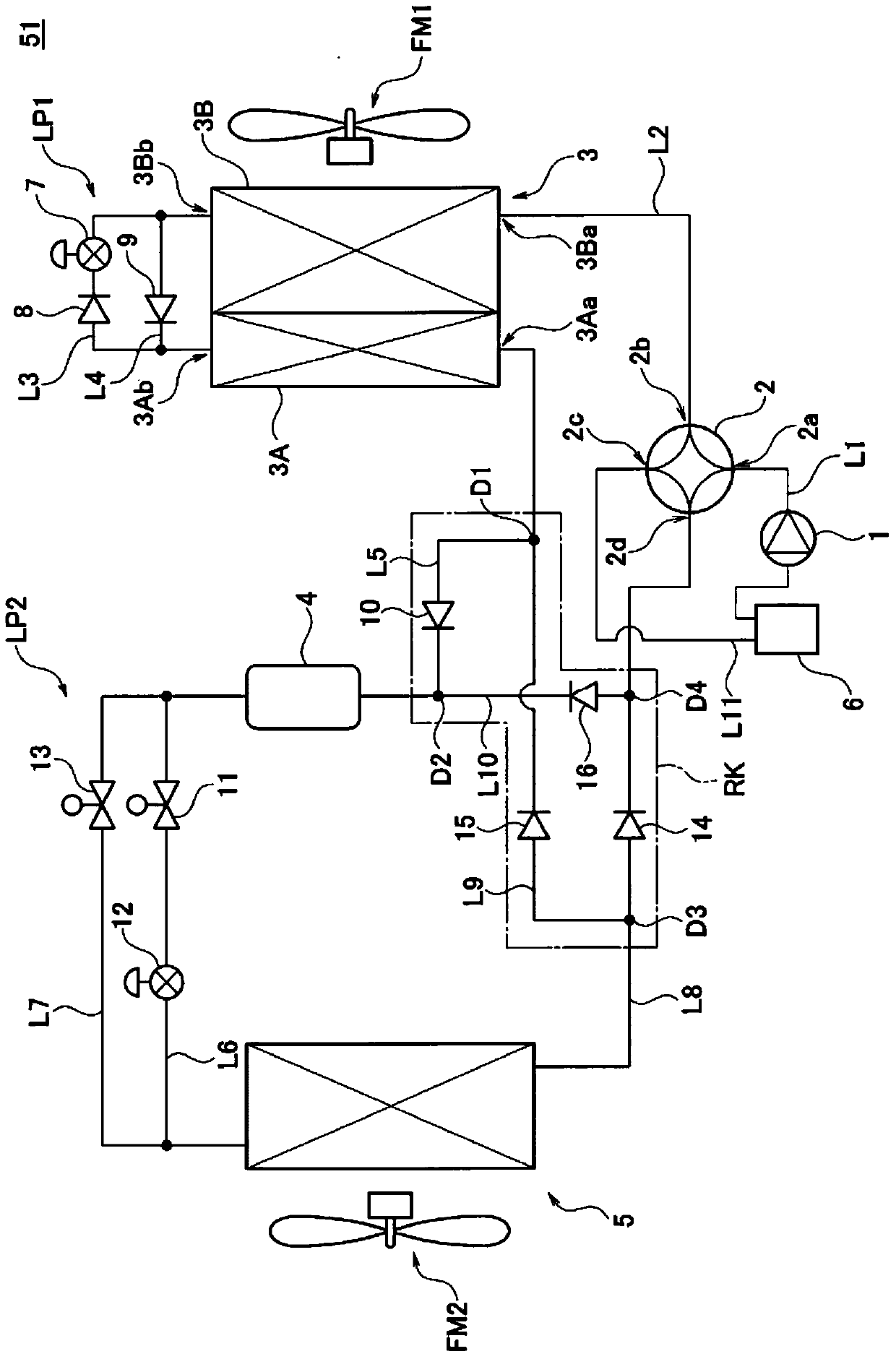
[0245] Modification 1 is to install a gas-liquid heat exchanger 17 for heat exchange between the piping line L6 on the upstream side and the piping line L8 on the downstream side of the internal heat exchanger 5 in the refrigerant circuit of the refrigeration device 51 of the embodiment. (refrigerating unit 51A) (refer to Figure 12 )example of. Figure 12 It mainly shows the refrigerant circuit with the refrigeration device 51 in the refrigerant circuit of the refrigeration device 51A (refer to figure 1 ) Partial circuit diagrams of the different parts.

[0246] The gas-liquid heat exchanger 17 is connected between the solenoid valve 11 and the expansion valve 12 with respect to the piping line L6. And it is connected between the interior heat exchanger 5 and the branch part D3 with respect to the piping line L8.

[0247] During the cooling operation of the refrigeration unit 51A, the refrigerant Figure 12 Flow in the direction of the arrow in the piping portion shown by...


PUM


Abstract

A refrigeration device enables sufficient warming by means of simple control and in a state of being free from influences of an operation environment. The device has a compressor, a flow path selection part which switches a refrigerant flow path to a first flow path or a second flow path selectively, an outside-of-warehouse heat exchanger, a flow direction restriction part which restricts a refrigerant flow direction relative to the outside-of-warehouse heat exchanger, a liquid receiver and an in-warehouse heat exchanger. Through selection of the first flow path, cooling operation is carried out, and a gaseous refrigerant is provided for the outside-of-warehouse heat exchanger by means of the compressor to give play to the function of a condenser. The in-warehouse heat exchanger is supplied with a liquid refrigerant from the outside-of-warehouse heat exchanger via the liquid receiver through utilization of restriction by the flow direction restriction part to give play to the function of an evaporator. Through selection of the second flow path, warming operation is carried out, and the in-warehouse heat exchanger is supplied with the gaseous refrigerant from the compressor via the liquid receiver to give play to the function of the condenser. The outside-of-warehouse heat exchanger is supplied with the liquid refrigerant from the in-warehouse heat exchanger through utilization of restriction by the flow direction restriction part to give play to the function of the evaporator.

Description

technical field [0001] The present invention relates to a refrigeration device and a method for operating the refrigeration device, in particular to a refrigeration device and a method for operating the refrigeration device capable of temperature-raising operation. Background technique [0002] As a refrigeration device, there is known a device that can perform not only a cooling operation but also a heating operation (see Patent Document 1). [0003] Refrigerators that can perform warm-up operation are mounted on, for example, refrigerated trucks and used to deliver food to convenience stores and the like. In this refrigerated truck, the refrigerating device mounted on it cools the interior when the set interior temperature is lower than the outdoor temperature during delivery, and cools the interior when the set interior temperature is higher than the outdoor temperature. to heat up. [0004] In this way, the temperature in the warehouse can be maintained at a constant t...

Claims


Application Information

Patent Timeline
Patent Type & Authority Patents(China)
IPC IPC(8): F25B1/00F25B39/00
CPCF25B13/00F25B39/00F25B2339/00
Inventor 藤野博之增野谦三平勇人
Owner TOPRE
Why Eureka
Try Eureka