Image forming apparatus

A technology of image and toner image, applied in the field of image forming device

Active Publication Date: 2012-05-23
KYOCERA DOCUMENT SOLUTIONS INC
View PDF4 Cites 0 Cited by
  • Summary
  • Abstract
  • Description
  • Claims
  • Application Information

AI Technical Summary

Problems solved by technology

[0007] However, if the area of ​​the shielding plate is too large, the magnetic field will be affected even if the shielding plate is in the withdrawn state
For example, when it is necessary to inductively heat the entire width of the heating roller, even if the shielding plate is retracted, if the magnetic field is blocked by the influence of the shielding plate at the retracted position, induction heating cannot be sufficiently performed, so it is not suitable.
Therefore, there is a limit to increasing the area of ​​the shielding plate even if the effect of suppressing excessive temperature rise is to be improved compared to the present

Method used


Image

  • Image forming apparatus
  • Image forming apparatus
  • Image forming apparatus

Examples


no. 1 approach

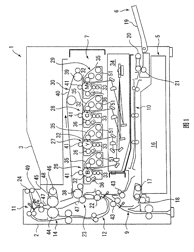
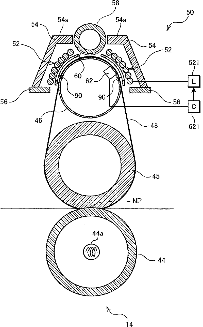
[0079] figure 2 It is a longitudinal sectional view showing the structure of the fixing unit 14 of the first embodiment. exist figure 2 , shows a state where the fixing unit 14 mounted on the image forming apparatus 1 is rotated about 90° in the counterclockwise direction. Thus, in figure 1 The feeding direction from bottom to top in figure 2 from right to left. In addition, in the case where the device main body 2 is larger (such as a digital composite machine), it may be installed as figure 2 orientation shown.

[0080] The fixing unit 14 has the pressure roller 44 , the fixing roller 45 , the heating roller 46 , and the heating belt 48 as described above. As described above, since the pressure roller 44 is a metal roller and the surface layer of the fixing roller 45 has an elastic layer of silicon sponge, a flat nip NP is formed between the pressure roller 44 and the fixing roller 45 . In addition, a halogen heater 44 a is provided inside the pressure roller 44 . T...

no. 2 approach

[0159] Next, details of the fixing unit 14 of the second embodiment will be described. Figure 16 It is a longitudinal sectional view showing the fixing unit 14 of the second embodiment. exist figure 2 Middle indicates a state where the fixing unit 14 actually mounted on the image forming apparatus 1 is rotated about 90° in the counterclockwise direction. Thus, in figure 1 In the direction of paper transport from bottom to top, in Figure 16 Middle is from right to left. In addition, in the case where the device main body 2 is larger (such as a digital composite machine), it may be Figure 16 Install in the orientation shown.

[0160] The fixing unit 14 includes a pressure roller 44, a fixing roller 45, and a heating belt 148 wound around its outer circumference. The pressure roller 44 is a metal roller, and the surface layer of the fixing roller 45 (inside the heating belt 148 ) has an elastic layer of silicon sponge, so a flat nip NP is formed between the pressure rol...

no. 3 approach

[0209] Figure 24A and Figure 24B It is a longitudinal sectional view showing a third embodiment of the fixing unit 14 . The third embodiment differs from the first and second embodiments in that the fixing unit 14 has an enclosed type IH coil unit 50 . In addition, the configuration of the magnetic adjustment member 160 may be the same as that of the second embodiment. Additionally, using the reference Figure 17 The magnetic adjustment unit described above can switch the magnetic adjustment member 160 between the shielding position and the withdrawn position.

[0210] That is, the fixing unit 14 of the third embodiment includes the pressure roller 44 and the heating roller 46 , and fixes the toner image while conveying the paper between their nips. In addition, since the heating roller 46 is a metal roller, this structure is suitable for fixing a monochrome image. However, it is also possible to form a flat nip NP between the heating roller 46 and the pressure roller 4...


PUM


Abstract

A fixing unit (14) of an image forming apparatus (1) includes a heating member (48) having a first area where a sheet does not come into contact with the heating member (48) and a second area where the sheet comes into contact with the heating member (48). The fixing unit (14) further includes a coil (52) forming a magnetic field, cores (54,56) forming a magnetic path near the coil (52), a nonmagnetic magnetism adjusting member (90) arranged on the magnetic path and having a closed frame, and a switcher (58,60) capable of switching the magnetism adjusting member (90) between a first state where the magnetism adjusting member (90) generates an induction current resulting from the magnetic field to shield the magnetism in the first area, and a second state where the magnetism adjusting member (90) generates no induction current and the magnetism is not shielded in the first area.

Description

technical field [0001] The present invention relates to an image forming apparatus having a fixing unit that passes a sheet carrying a toner image between a pair of heating rollers or a gap between a heating belt and a roller, and heats, melts and fixes unfixed toner on the sheet. Background technique [0002] In recent years, from the viewpoints of shortening the warm-up time of the fixing unit and saving energy, attention has been paid to adopting a belt system capable of reducing heat capacity in image forming apparatuses (for example, refer to Japanese Patent Application Laid-Open No. Hei 6-318001). In addition, in recent years, the electromagnetic induction heating method (IH) that can heat quickly and efficiently has also attracted attention. From the perspective of energy saving during color image fixing, many products that combine the electromagnetic induction heating method and the belt method have been produced. In the case of combining the belt method and the ele...

Claims


Application Information

Patent Timeline
Patent Type & Authority Patents(China)
IPC IPC(8): G03G15/20G03G15/01
Inventor 南条让中嶋荣次近藤昭浩石田直行权钟浩笠间健一
Owner KYOCERA DOCUMENT SOLUTIONS INC
Why Eureka
Try Eureka