Passive aircraft wingtip strike detection system and method

An aircraft and wingtip technology, applied in the field of aircraft wingtip collision prevention, can solve problems such as the probability of collision accidents and the increase in cost

Active Publication Date: 2015-08-05
HONEYWELL INT INC
View PDF5 Cites 2 Cited by
  • Summary
  • Abstract
  • Description
  • Claims
  • Application Information

AI Technical Summary

Problems solved by technology

The probability and cost of a crash accident increases as the size of the aircraft increases

Method used


Image

  • Passive aircraft wingtip strike detection system and method
  • Passive aircraft wingtip strike detection system and method
  • Passive aircraft wingtip strike detection system and method

Examples


Embodiment Construction

[0017] The following specific embodiments are merely exemplary in nature, and are not intended to limit the present invention or application and the use of the present invention. As used herein, the word "exemplary" means "serving as an example, instance, or illustration." Therefore, any embodiment described herein as "exemplary" is not necessarily construed as being preferred or advantageous for other embodiments. All the embodiments described herein are exemplary embodiments, which are provided to enable those skilled in the art to make or use the present invention, and are not used to limit the scope of the invention defined by the claims. In addition, it is not intended to be bounded by any expression or implied theory presented in the previous technical field, background technology, summary of the invention or the following specific embodiments.

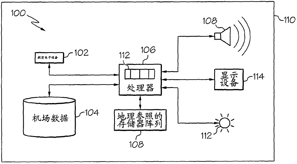
[0018] First refer to figure 1 , Depicts a functional block diagram of an embodiment of the passive wingtip impact detection sys...


PUM


Abstract

A system and method for passively detecting aircraft wingtip strikes includes generating a digital base map represented by a plurality of aerodrome cells. A numeric value is assigned to each of the aerodrome cells that is representative of the specific wingtip strike threat associated with that aerodrome cell. An index count array is generated that has a separate entry for each numeric value. A digital aircraft structure is generated that is representative of an aircraft, and is represented by a plurality of aircraft cells. A portion of the aerodrome cells are replaced with the plurality of aircraft cells. Each numeric value of the aerodrome cells that are replaced is counted to determine a replacement count associated therewith and that is entered into the separate entry in the index count array for that numeric value. One or more potential aircraft wingtip strikes are detected based on the replacement counts.

Description

[0001] Cross references to related applications [0002] This application claims the rights of U.S. Provisional Application No. 61 / 933,335 filed on January 30, 2014. Technical field [0003] This application relates generally to aircraft wingtip impact prevention, and more particularly to systems and methods for passively detecting aircraft wingtip impact. Background technique [0004] Aircraft pilots usually control the aircraft while on the ground. This can occur during ground operations, such as when the aircraft is taxiing, being maneuvered to or from a hangar, or to or from a terminal. [0005] Obstacles on the ground, such as structures, other vehicles and other obstacles, may be in the path of the aircraft. The pilot can detect these obstacles through the line of sight. However, in many cases, it may be difficult to monitor the end of the aircraft during ground operations due to the size of the aircraft (e.g., large wing sweep angle, distance from the cockpit to the wingtip)...

Claims


Application Information

Patent Timeline
Patent Type & Authority Applications(China)
IPC IPC(8): G08G5/04
CPCG08G5/0021G09B29/007G05D1/0083G09B29/10G08G5/065G08G5/0086G08G5/06G08G5/0078G05D1/0274G08G5/04G09B9/052G09B29/006
Inventor K·J·康纳Y·伊施哈拉S·约翰逊R·贝里
Owner HONEYWELL INT INC
Why Eureka
Try Eureka