Image capturing system for shape measurement of structure, on-board controller

a technology of image capturing and structure, applied in the direction of process and machine control, instruments, etc., can solve the problems of affecting the accuracy of image capturing, gps may not be used during image capturing, and the air vehicle may not be able to fly autonomously in a non-gps environment, so as to achieve efficient image capture

Active Publication Date: 2021-05-25
MITSUBISHI ELECTRIC CORP
View PDF6 Cites 1 Cited by
  • Summary
  • Abstract
  • Description
  • Claims
  • Application Information

AI Technical Summary

Benefits of technology

[0008]An object of the present invention is to provide an image capturing system for shape measurement of a structure, which is capable of efficiently capturing an image for shape measurement of a structure even in an environment where GPS cannot be used, and an on-board controller.
[0011]According to the present invention, the shape measurement of the structure can be performed efficiently in a short period of time in accordance with the predetermined flight scenario. Moreover, the flight of the air vehicle and the measurement of the structure can be performed even in an environment where GPS cannot be used.

Problems solved by technology

However, it has been difficult for the air vehicles to fly autonomously in a non-GPS environment such as a closed space where a GPS signal cannot be received.
In the case of a large-sized structure such as a high-precision parabolic antenna, the large-sized structure needs to be assembled indoors once during production in order to verify precision, and GPS may be unable to be used during image capturing.
There is also a problem of fluctuation in a GPS signal even during flight in the GPS environment, resulting in degradation in positional precision.
In addition, information acquired by the measurement instrument needs to be transformed to GPS coordinates, resulting in poor real-time performance.
It is also assumed that a method of simply reflecting a light wave from a position measurement instrument such as a total station has difficulty in position measurement depending on the flight angle and flight position.
In addition, the cameras may not be able to capture images of the marker successfully if there are obstacles on a flight path.

Method used


Image

  • Image capturing system for shape measurement of structure, on-board controller
  • Image capturing system for shape measurement of structure, on-board controller
  • Image capturing system for shape measurement of structure, on-board controller

Examples


first embodiment

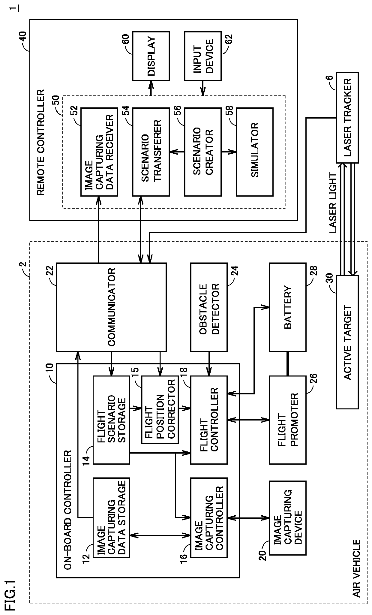
[0030]FIG. 1 is a block diagram showing a configuration of an image capturing system for shape measurement of a structure according to a first embodiment. An image capturing system 1 for shape measurement of a structure includes: an image capturing device 20 configured to capture an image of the structure; an air vehicle 2; an on-board controller 10 mounted on air vehicle 2; a remote controller 40 configured to transfer data to on-board controller 10; and a laser tracker 6 serving as a ground measurement instrument configured to measure a position of the air vehicle. Air vehicle 2 is a pilotless airplane having image capturing device 20 mounted thereon. Air vehicle 2 is configured to fly and hover. Examples of air vehicle 2 usable herein include a drone, a multicopter, and an UAV. Image capturing system 1 for shape measurement further includes a communicator 22, an obstacle detector 24, a flight promoter 26, a battery 28, and an active target 30, which are mounted on air vehicle 2.

[...

second embodiment

[0093]In the first embodiment, one laser tracker 6 and one air vehicle 2 are used. In a second embodiment, a plurality of laser trackers 6 and a plurality of air vehicles 2 are used and managed in accordance with different flight scenarios. As a result, the entire structure can be readily measured.

[0094]FIG. 11 is a conceptual diagram representing a usage scene of an image capturing system for shape measurement according to the second embodiment. As shown in FIG. 11, a plurality of laser trackers 6A, 6B are prepared, and a plurality of air vehicles 2A, 2B are prepared. It should be noted that air vehicles 2A, 2B may have a similar configuration to that of air vehicle 2 shown in FIGS. 1 to 6. A different flight scenario is created based on a 3D model for each of air vehicles 2A, 2B. The two flight scenarios are created such that some (10 to 50%, for example) of their measurement locations overlap each other. The same 3D model may be used for the creation, or different models (models ...

third embodiment

[0097]In the second embodiment, a plurality of laser trackers and a plurality of air vehicles are used. In a third embodiment, a plurality of laser trackers and one air vehicle are prepared and managed. As a result, a shape which is difficult to track with laser light from one laser tracker can be measured in a short period of time.

[0098]FIG. 12 is a conceptual diagram representing a usage scene of an image capturing system for shape measurement according to the third embodiment. An air vehicle 2C flies from a flight start point based on a flight scenario 65C, while correcting its flight position based on tracking by a laser tracker 6C. Then, air vehicle 2C hovers at a switching position 150 where the laser tracker is switched, and switches the tracking by laser tracker 6C to tracking by a laser tracker 6D. Air vehicle 2C also switches the coordinate system from a coordinate system 70C to a coordinate system 70D, and continues the flight based on a flight scenario 65D, while correct...


PUM


Abstract

A laser tracker is installed on the ground, and an active target is mounted on an air vehicle. A reference coordinate system is set for the laser tracker, and a flight scenario created in advance based on a 3D model is used. Flight of the air vehicle is performed while an amount of deviation from the flight scenario is being calculated using position information obtained by the laser tracker, and corrections are being made. The air vehicle is instructed not only on an amount of movement but also on speed, so that efficient flight can be performed in consideration of battery capacity.

Description

CROSS REFERENCE TO RELATED APPLICATIONS[0001]The present application is based upon and claims the benefit of priority to Japanese Patent Application No. 2018-067138 filed on Mar. 30, 2018, the entire contents of which are incorporated herein by reference.BACKGROUND OF THE INVENTIONField of the Invention[0002]The present invention relates to a system for capturing an image of a structure for shape measurement of the structure using an image capturing device mounted on an air vehicle.Description of the Background Art[0003]In recent years, there have been proposed various systems for measuring geographical features or the like using image capturing devices mounted on mainly remotely controlled air vehicles, such as a drone, a multicopter, and an UAV (Unmanned Air Vehicle). On the other hand, in a photographic measurement system, an air vehicle used therein is controlled by human being or is guidance-controlled based on GPS (Global Positioning System). Geographical feature and aerial ph...

Claims


Application Information

Patent Timeline
Patent Type & Authority Patents(United States)
IPC IPC(8): G01C23/00G05D1/00G05D3/00G06F7/00G06F17/00G05D1/10G06T7/521B60R11/04G06F30/00
CPCG05D1/101B60R11/04G06F30/00G06T7/521G05D1/102
Inventor IWAKURA, TAKASHIISHIDA, TAKAYUKI
Owner MITSUBISHI ELECTRIC CORP
Why Eureka
Try Eureka