X-ray CT device and image displaying method therefor

a ct device and image display technology, applied in the field of xray ct devices, can solve the problems of excessive or insufficient amount of transmitted x-rays, excessive x-ray amount in the liver, excessive x-ray amount in the lungs, etc., and achieve the effect of effectively utilizing the past ct images and shortening the time for generating the body ct value models

Inactive Publication Date: 2006-09-05
FUJIFILM HEALTHCARE CORP
View PDF5 Cites 48 Cited by
  • Summary
  • Abstract
  • Description
  • Claims
  • Application Information

AI Technical Summary

Benefits of technology

[0035]In the X-ray CT device of the present invention, the above-described means for generating a CT value model of the body being examined further generates the three-dimensional CT value model of the body being examined from the CT images obtained by the past CT scanning of the body being examined. With this construction, since the three-dimensional CT value model data of the body being examined is obtained from the past CT image of the body being examined, the time for generating the body CT value model can be shortened by effectively utilizing the past CT images.

Problems solved by technology

Therefore, a problem exists in that the amount of transmitted X-rays may be excessive or insufficient while scanning one cross-section.
Therefore, a the scan is continuously performed from the chest to the abdomen and an X-ray amount suitable for the lungs is set, the X-ray amount will be insufficient for the liver.
In contrast to this, when an X-ray amount suitable for the liver is set, the X-ray amount will be excessive in the lungs.
When the transmitted X-ray amount is insufficient, the S / N (SN ratio) becomes worse because of the reduced amount of X-ray photons detected by the X-ray detector (hereinafter abbreviated as a detector), and the S / N of the entire cross-sectioned image obtained by image reconstruction becomes worse as a result.
Conversely, when the transmitted X-ray amount is too large, unnecessary X-rays are applied to the body being examined.
However, the method for controlling the tube voltage as described in JP-A-53-110495 has a problem in that, during the scan, the spectrum of the X-rays is changed, since the tube voltage is changed, and thus the CT value cannot be determined.
However, the method using the data of X-ray passage through the object in the first half of the scanner rotation, as described in JP-A-10-309271, has a problem in that the X-ray data deviates from one cross-section to another, particularly in a helical scan with a large scan pitch.
Further, this method cannot cope with an area in which the X-ray absorption characteristics of the body being examined vary greatly e.g. above and below the diaphragm.
Accordingly, this method is contrary to its purpose, i.e. reduction of the exposure through tube current control.
However, there is no consideration of the actual amount of X-rays being applied to the body by this set tube current or the X-rays received by the internal organs within the body.

Method used


Image

  • X-ray CT device and image displaying method therefor
  • X-ray CT device and image displaying method therefor
  • X-ray CT device and image displaying method therefor

Examples


Embodiment Construction

[0050]Various embodiments of the present invention will be explained with reference to the accompanying drawings.

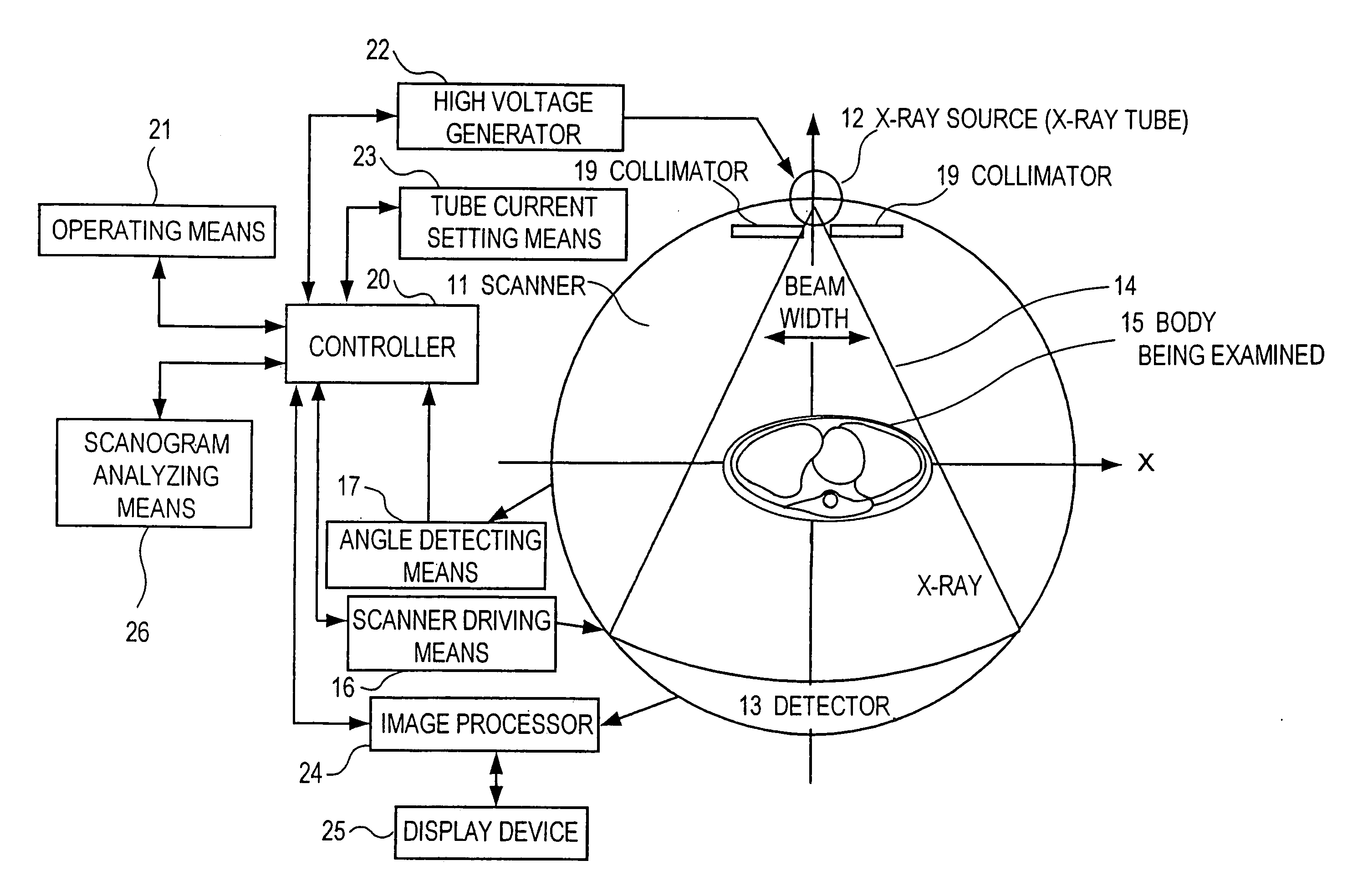
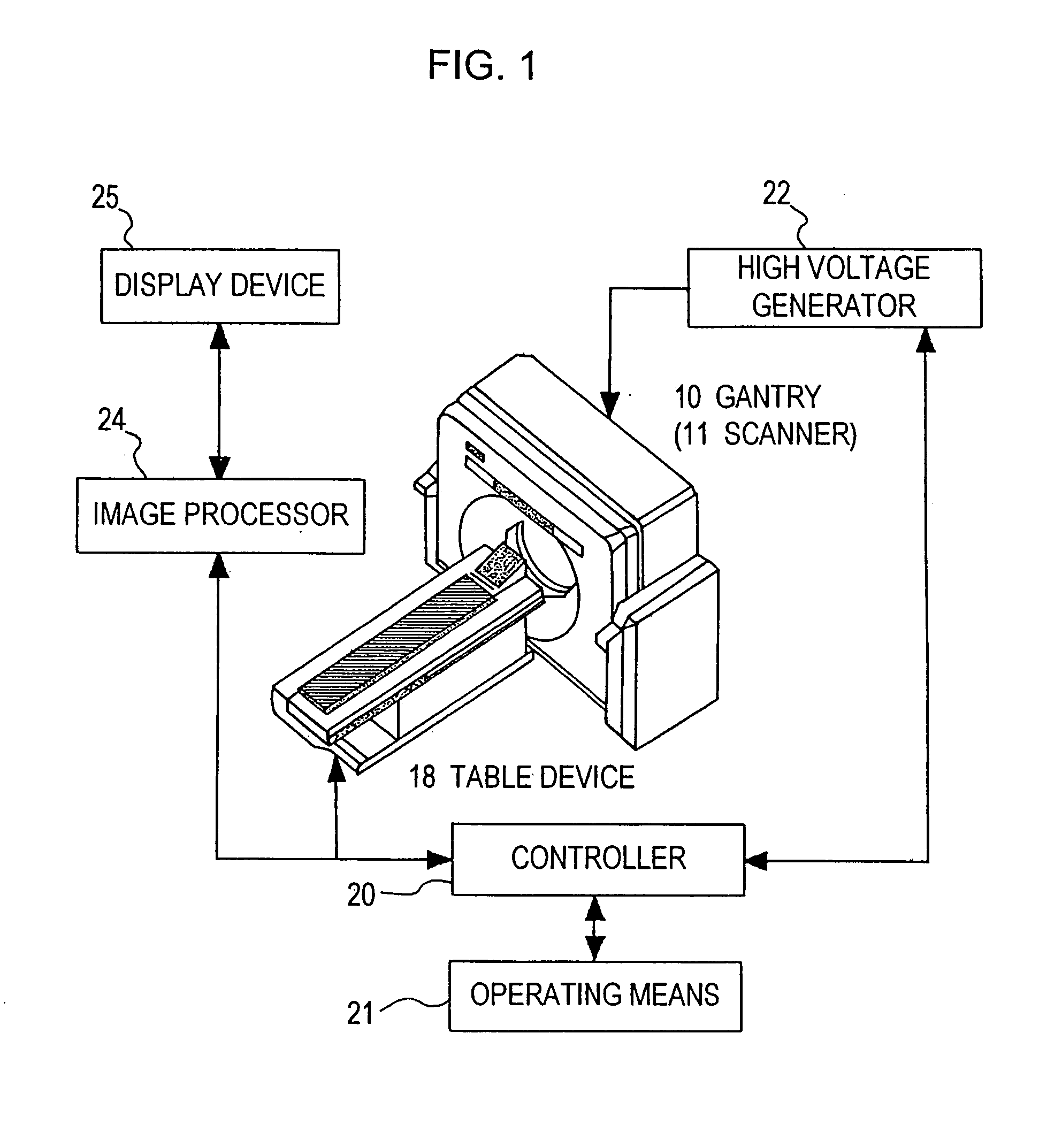
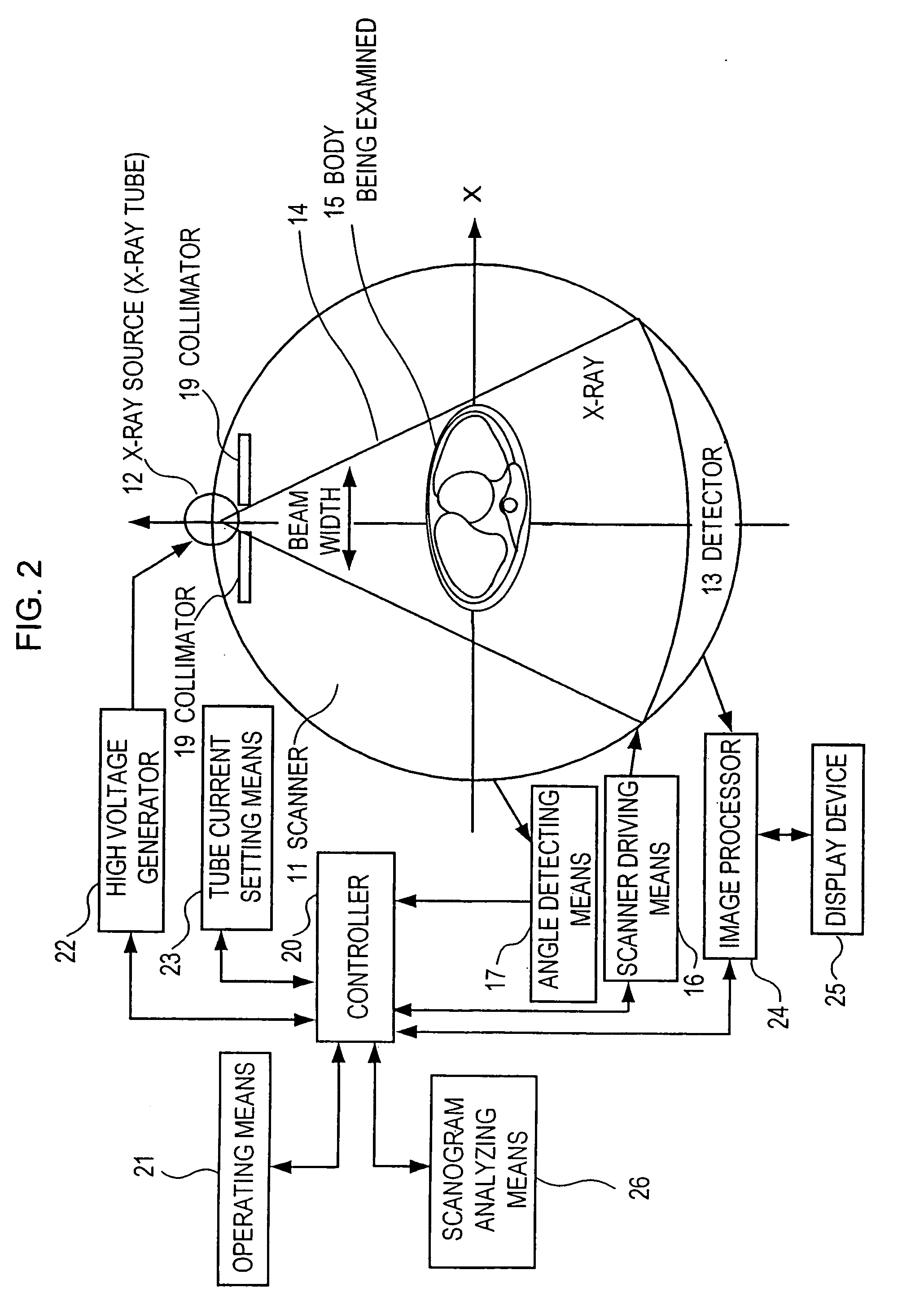
[0051]FIG. 1 is a block diagram showing the overall construction of an X-ray CT device in accordance with the present invention. As shown in FIG. 1, this X-ray CT device is mainly constructed by a gantry 10 mounting an X-ray source 12, a detector 13, etc., and having a built-in scanner 11 that is able to be continuously rotated around a body 15 being examined, a controller 20 for overall control of the device, a high voltage generator 22 for supplying a high voltage to the X-ray source 12, an image processor 24 for performing preprocessing and reconstruction of image data or other various kinds of analysis, a display device 25 for displaying an image, a bed (table device) 18 upon which the body 15 being examined is placed, and an operating means 21 for use by an operator to input scan conditions, etc. It is sufficient to rotate the scanner 11 and the body 15 being examine...


PUM

PropertyMeasurementUnit
densityaaaaaaaaaa
linear attenuation coefficientaaaaaaaaaa

Abstract

In an X-ray CT device, the scan conditions of the device are set, a three-dimensional X-ray passage length model of the body being examined is generated from a scanogram image of the body, the control pattern of the tube current is automatically set on the basis of the scan conditions and the three-dimensional passage length model, and the dose which will be given will be calculated and displayed on the basis of the control pattern of the tube current, and three-dimensional CT value model data of the body generated on the basis of a standard human body. The scanogram image of the body and the control pattern of the tube current are displayed next to each other or overlap to allow an operator to edit the control pattern while viewing the body, so that a suitable tube current can be set.

Description

TECHNICAL FIELD[0001]The present invention relates to an X-ray CT device which controls the exposure of X-rays applied to an object to be examined by controlling the electric current (tube current) supplied to an X-ray source (X-ray tube) during scanning and, more particularly, the invention relates to a technique which makes it possible to set the curve of a change in the tube current during the scanning in consideration of the dose of X-rays given to the object and the image quality.BACKGROUND OF THE INVENTION[0002]In a conventional X-ray CT device, the scan conditions, including the tube voltage and the tube current supplied to the X-ray tube, are kept constant while scanning the same cross-section.[0003]Further, a helical scan for taking a photograph by scanning the body being examined along a spiral path has been widely used in recent years, but the conditions of scanning in the body axis direction are maintained constant during such a scan.[0004]Accordingly, for example, when ...

Claims


Application Information

Patent Timeline
Patent Type & Authority Patents(United States)
IPC IPC(8): G01N23/00A61B6/03
CPCA61B6/032A61B6/463A61B6/542A61B6/469A61B6/488A61B6/466
Inventor NAGAOKA, TAKAYUKIMIYAZAKI, OSAMU
Owner FUJIFILM HEALTHCARE CORP
Why Eureka
Try Eureka