Method and system for automatically calibrating a color-based machine vision system

automatic calibration technology, applied in the field of methods and systems for automatically calibrating a color-based machine vision system, can solve problems such as sample rate jitter, quantization error, and rate jitter

Inactive Publication Date: 2000-01-18
INTEGRAL VISION +1
View PDF16 Cites 47 Cited by
  • Summary
  • Abstract
  • Description
  • Claims
  • Application Information

AI Technical Summary

Benefits of technology

Color temperature effects on color rendition;
1. Spatially distributed unevenness in illumination level,
2. Spatially distributed unevenness in spectral content,
Temporal changes in illumination (short term);
This effect has crucial implications when attempting to use camera 22 as a color measuring sensor. On initial set up, the camera 22 can be adjusted to the color temperature of the supplied illumination source 26 by modifying the individual color channel gains such that imaging a white surf

Problems solved by technology

There are two distinct types of digitization noise, these being sample rate jitter, and quantization error.
Sample rate jitter is caused by an inaccurately timed and jittering sample rate clock.
This has the effect of producing irregular sampling along the incoming video signal; and results in geometric distortion of the sampled image.
However, in the machine color vision field where a camera, generally indicated at 22, is being used as a color

Method used


Image

  • Method and system for automatically calibrating a color-based machine vision system
  • Method and system for automatically calibrating a color-based machine vision system
  • Method and system for automatically calibrating a color-based machine vision system

Examples


Embodiment Construction

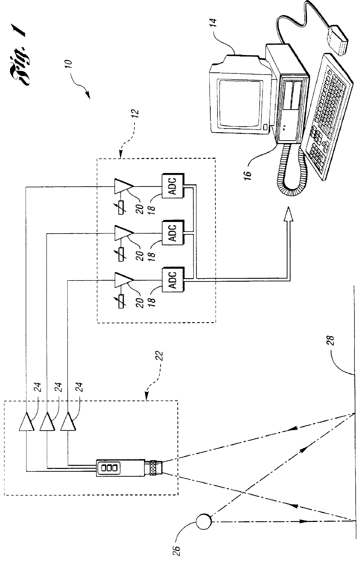
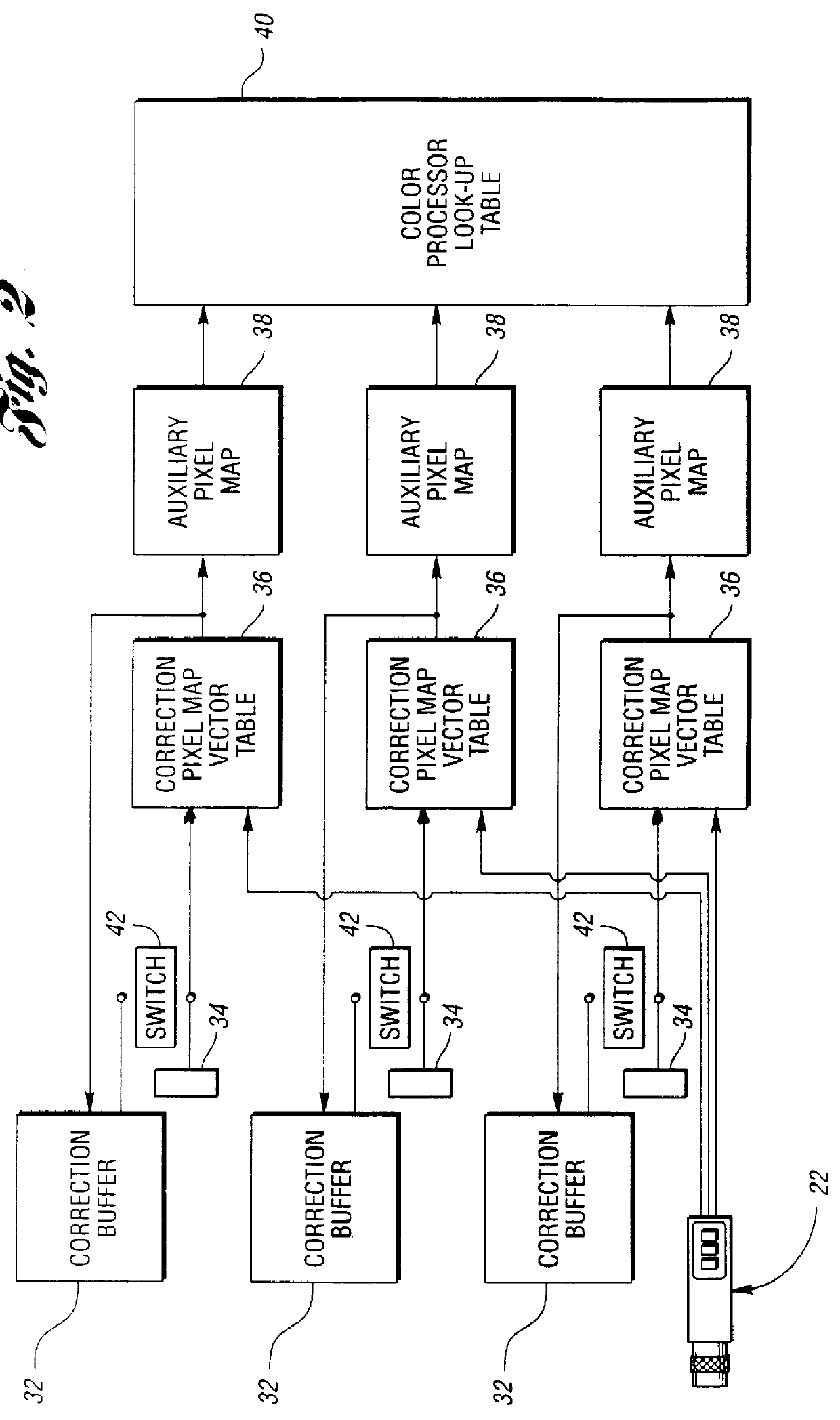
Referring now to FIG. 2, there is illustrated schematically a system, generally indicated at 30, of the present invention which can automatically calibrate the machine vision system 10 of FIG. 1. While RGB cameras are most widely used in such a system 10, the method and system of the present invention could also be used with cameras having other types of channels such as Cyan, Magenta and Yellow channels. The camera 22 may be an image source such as an analog, digital or line scan camera such as RS-170, CCIR, NTSC and PAL.

The system 30, which preferably takes the form of an appropriately programmed computer such as the computer 16, includes three parallel subsystems. Each subsystem includes an 8 bit wide correction buffer 32 of sufficient capacity to hold one complete image. Each subsystem also has a single location 8 bit constant register 34. The contents of either the correction buffer 32 or the constant register 34 of each subsystem can be switched through to one-half of a correc...


PUM


Abstract

A calibration algorithm is provided for calibrating a machine vision system including a color camera, a framegrabber and an illumination source wherein subsequently acquired images are processed on a pixel-by-pixel basis. After framegrabber offsets are measured to obtain initial or offset calibration data, the camera is pointed at a target monotone patch of known reflectance such as pure white and the camera outputs for red, green and blue are determined while observing the monotone patch to obtain spatial calibration data. The gain for each of the output channels of the color camera is automatically determined from the initial calibration data. Applying the three gain factors to a subsequent image on the pixel-by-pixel basis allows one to end up with a color-corrected image without incurring any time performance penalty. At any time during an inspection process, a small area of white reflectance can be observed. The resulting dynamic white calibration data is used to correct for any medium to long term temporal variation in imaging conditions.

Description

That application describes an automatic calibration methodology which provides the ability to compensate for variations in the color temperature of an illumination source and the statistical process by which the color characteristics of the image being grabbed by the machine vision system could be compared with a perfectly color balanced version of the same image. The grabbed image then being processed so that the color balance of the incoming images matches that of the template image.That application also describes an algorithm where a master comparison image is defined to be an area of featureless white, and correction factors required to compensate for color channel gains are directly computed from that section of the image. This algorithm is very effective in removing gain variations from the image capture chain and ensuring consistent imaging results from a number of imaging stations. However, many of the imaging artifacts described hereinbelow are not dealt with and often thei...

Claims


Application Information

Patent Timeline
IPC IPC(8): H04N9/73H04N17/00G01J5/48G01J3/50G01J5/60G06T1/00H04N9/04H04N17/02
CPCH04N9/735H04N17/002H04N23/88
Inventor ROBINSON, DAVID A.
Owner INTEGRAL VISION
Why Eureka
Try Eureka