LED display screen device and displaying method thereof

A LED display and display panel technology, applied to static indicators, instruments, etc., can solve the problems of not being able to further increase the operating speed and reduce storage space, and achieve the effect of avoiding data repetition and reducing storage space

Inactive Publication Date: 2015-08-12
包健
View PDF6 Cites 2 Cited by
  • Summary
  • Abstract
  • Description
  • Claims
  • Application Information

AI Technical Summary

Problems solved by technology

However, this technical solution is still based on the independence of pictures and paths, which cannot further improve the running speed and reduce storage space

Method used


Image

  • LED display screen device and displaying method thereof
  • LED display screen device and displaying method thereof

Examples


Embodiment 1

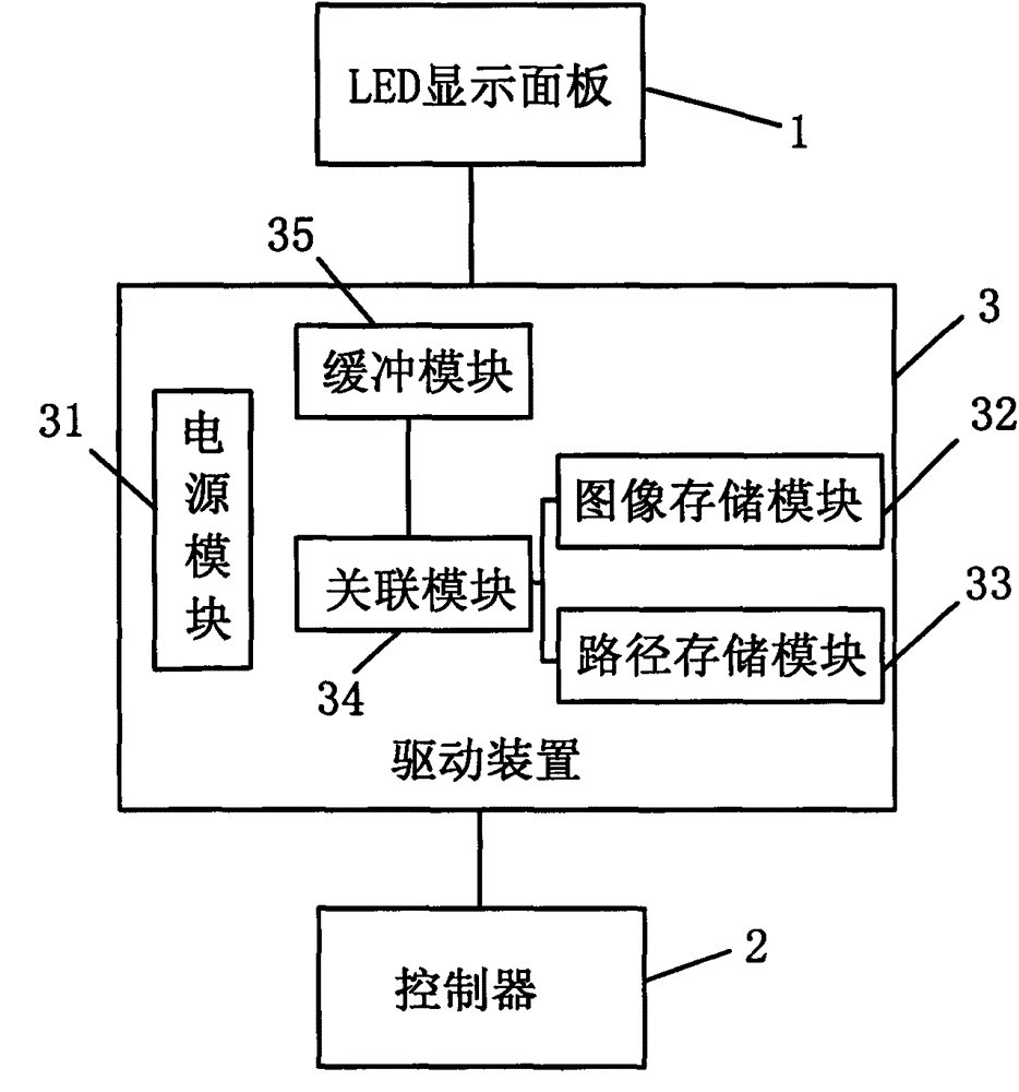
[0019] refer to figure 1 , a kind of LED display device, comprises LED display panel 1 and controller 2, is provided with driving device 3 between LED display panel 1 and controller 2, and driving device 3 comprises power supply module 31, image storage module 32, path storage Module 33, association module 34 and buffer module 35, image storage module 32 and path storage module 33 are respectively connected to association module 34, association module 34 is connected to LED display panel 1 through buffer module 35, mains power supply to LED through power supply module 31 The display panel 1 supplies power, and the controller 2 is respectively connected to the image storage module 32 , the path storage module 33 and the association module 34 . Wherein, the controller 2 adopts the S7-200 series PLC of Siemens Company, of course, it can also be realized by other methods similar to single-chip microcomputer or industrial PC, which will not be described in detail here. The power s...

Embodiment 2

[0030] The hardware structure of this embodiment is the same as that of Embodiment 1, and will not be described in detail here.

[0031] The method for displaying using the device includes the following steps:

[0032] A. Store the image to be displayed into the image storage module 32 through the controller 2, and store the image display path into the path storage module 33;

[0033] B. The association module 34 retrieves the corresponding image from the image storage module 32 according to the display command input by the controller 2, and retrieves the corresponding image display path from the path storage module 33, and associates the image with the image display path through the buffer Module 35 output;

[0034] C, the association module 34 carries out the degree of association sorting of the paths associated with the different images displayed at the same time, establishes the mapping relationship of the path coordinates, and records it in the buffer module 35, and the ...

Embodiment 3

[0040] The hardware structure of this embodiment is the same as that of Embodiment 1, and will not be described in detail here.

[0041] The method for displaying using the device includes the following steps:

[0042] A. Store the image to be displayed into the image storage module 32 through the controller 2, and store the image display path into the path storage module 33;

[0043] B. The association module 34 retrieves the corresponding image from the image storage module 32 according to the display command input by the controller 2, and retrieves the corresponding image display path from the path storage module 33, and associates the image with the image display path through the buffer Module 35 output;

[0044] C, the association module 34 carries out the degree of association sorting of the paths associated with the different images displayed at the same time, establishes the mapping relationship of the path coordinates, and records them in the buffer module 35, and th...


PUM


Abstract

The invention discloses an LED display screen device, which comprises an LED display panel and a controller. A driving device is arranged between the LED display panel and the controller, and comprises a power supply module, an image storing module, a path storing module, an association module, and a buffer module, wherein the image storing module and the path storing module are connected to the association module, respectively; the association module is connected to the LED display panel via the buffer module; a mains supply powers the LED display panel via the power supply module; and the controller is connected to the image storing module, the path storing module, and the association module, respectively. The invention also discloses a displaying method of the LED display screen device, and the method combines an image and a display path. According to the invention, deficiencies in the prior art are overcome; the display speed is further increased by changing the combination mode of the image and the display path; and the storage space needed by data is greatly reduced.

Description

technical field [0001] The invention relates to the technical field of LED display, in particular to an LED display device and a display method thereof. Background technique [0002] The traditional LED display control system needs to divide the animation into multiple complete pictures when displaying dynamic images, and then store all the pictures in the LED display control system. Because this method requires a large number of pictures to display a continuous animation, the main disadvantage is that it takes up a lot of storage space of the LED display controller, and it is easy to cause the animation to be unable to be displayed due to insufficient storage capacity, and the calling speed is slow. Adapt to rapidly changing image requirements. In the prior art, Chinese invention patent CN 100530339C discloses a display method of a mobile terminal, and the display speed is improved through the use of scripts. However, this technical solution is still based on the mutual i...

Claims


Application Information

Patent Timeline
Patent Type & Authority Applications(China)
IPC IPC(8): G09G3/32
Inventor 包健马跃
Owner 包健
Why Eureka
Try Eureka