Paper extraction box

A paper-drawing box and paper-drawing opening technology, which is applied in the field of paper-drawing boxes, can solve the problems of low production cost and unsatisfactory continuous paper-drawing.

Inactive Publication Date: 2015-08-19
闫向洲
View PDF0 Cites 0 Cited by
  • Summary
  • Abstract
  • Description
  • Claims
  • Application Information

AI Technical Summary

Problems solved by technology

[0002] The existing folding paper pumping box technology does not meet the requirements of ensuring continuous paper pumping and low production costs

Method used


Image

  • Paper extraction box

Examples


Embodiment Construction

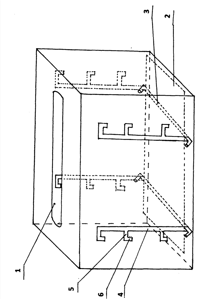
[0008] As shown in the attached figure, the box body is a cuboid with a paper-drawing hole on it, and two shifting slots are opened on the two sides with short distances, and the shifting slots are located on the sides of the 3 quadrants. Near the left and right sides, the four shifting slots are symmetrical in pairs, and the two supporting rods are interspersed in the shifting slots, the bottom of the box is placed on the supporting bars, and the origami is placed on the bottom of the box.


PUM


Abstract

The invention relates to a paper extraction box. A paper extraction opening is reserved in the upper face of a box body. The box bottom is movable, and convenience is brought to continuous paper extraction. The paper extraction box is characterized in that the bottom of the box body is separated from the box body, and the lower edges of the four lateral faces of the box body are inwards folded; the inner diameter of the bottom of the box body is slightly smaller than the inner diameter of the box body, and the bottom of the box body is supported through two supporting rods; the two supporting rods are inserted into four gear shifting grooves in two opposite lateral faces of the box body, and slippage of the four ends of the two supporting rods is limited through a T shape or an L shape; and each gear shifting groove comprises a gear shifting section, a deviation section and a positioning groove, and each gear shifting section is in the up-and-down direction. According to the paper extraction box, up-and-down gear shifting can be achieved through the supporting rods in the gear shifting grooves, the box bottom moves up and down, it is guaranteed that remaining paper is close to the upper opening, and therefore paper extraction is smooth.

Description

technical field [0001] Clean utensils. Background technique [0002] The existing folding paper pumping box technology does not meet the requirements of ensuring continuous paper pumping and low production cost. Contents of the invention [0003] The object of the present invention is to provide a folding paper pumping box with reliable operation and low production cost. [0004] The technical solution adopted in the present invention is: a paper-drawing opening is left on the top of the paper-drawing box, the bottom of the box body is separated from the box body, the lower edges of the four sides of the box body are retracted inward, and the bottom of the box body is slightly smaller than According to the size of the box body, the bottom of the box body is held up by two support rods, and the two support rods are inserted in the four shifting grooves on the two opposite sides of the box body. The four ends of the two support rods are connected by T-shaped or L-shaped li...

Claims


Application Information

Patent Timeline
Patent Type & Authority Applications(China)
IPC IPC(8): A47K10/20
Inventor 闫向洲
Owner 闫向洲
Why Eureka
Try Eureka