Stretching mechanism, material sliding groove and stirring trolley

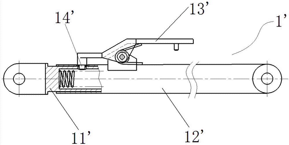
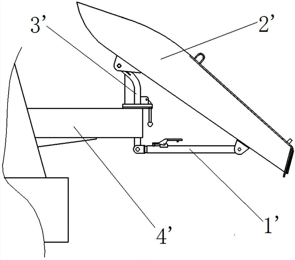
A technology of telescopic mechanism and slide trough, which is applied in the direction of cement mixing device, unloading device, clay preparation device, etc. It can solve the problems of inconvenient operation, high failure rate of telescopic mechanism 1', and stuck limit handle.

Inactive Publication Date: 2015-08-19
BEIQI FOTON MOTOR CO LTD
View PDF14 Cites 4 Cited by
  • Summary
  • Abstract
  • Description
  • Claims
  • Application Information

AI Technical Summary

Problems solved by technology

[0005] 1. At present, when positioning the length of the telescopic mechanism 1', the positioning pin 14' on the limit handle 13' on the sliding outer tube 12' is inserted into the through hole on the fixed inner tube 11', so the telescopic mechanism 1 The length change of 'is limited by the position and number of positioning holes on the fixed inner tube 11'
[0006] 2. In order to lift the sliding chute 2' to a suitable height, the operator needs to lift the sliding chute 2' with one hand to adjust the height, and the other hand to operate the limit handle 13', which is low in efficiency and difficult to operate. It's extremely inconvenient
[0007] 3. Due to the harsh working environment of the mixer truck, concrete and cleaning sewage are likely to splash on the telescopic mechanism 1', and the concrete is dry and hard, causing the limit handle 13' to be stuck, and the limit is not flexible
Concrete and cleaning sewage enter the telescopic mechanism 1' from the opening of the telescopic mechanism, causing the fixed inner pipe 11' and the sliding outer pipe 12' to be stuck and corroded, and the failure rate of the telescopic mechanism 1' is high

Method used


Image

  • Stretching mechanism, material sliding groove and stirring trolley
  • Stretching mechanism, material sliding groove and stirring trolley
  • Stretching mechanism, material sliding groove and stirring trolley

Examples


Embodiment Construction

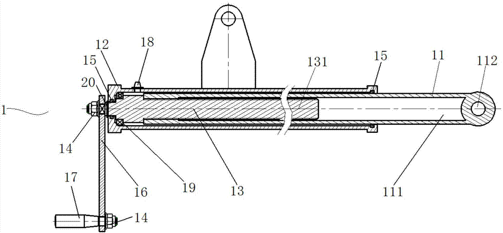
[0031] In order to make the objectives, technical solutions and advantages of the present invention clearer, the technical solutions in the embodiments of the present invention will be described in more detail below in conjunction with the drawings in the embodiments of the present invention. In the drawings, the same or similar reference numerals denote the same or similar elements or elements having the same or similar functions throughout. The described embodiments are some, but not all, embodiments of the invention. The embodiments described below by referring to the figures are exemplary and are intended to explain the present invention and should not be construed as limiting the present invention. Based on the embodiments of the present invention, all other embodiments obtained by persons of ordinary skill in the art without creative efforts fall within the protection scope of the present invention. Embodiments of the present invention will be described in detail below ...


PUM


Abstract

The present invention discloses a stretching mechanism, a material sliding groove and a stirring trolley, wherein the stretching mechanism comprises a stretching inner pipe, a fixed outer pipe sleeved outside the stretching inner pipe, and a drive mechanism positioned in the fixed outer pipe, and the stretching inner pipe performs continuous stretching movement relative to the fixed outer pipe along the axial direction under the driving force effect of the drive mechanism. According to the present invention, the continuous adjusting can be achieved within a certain length range so as to provide the beneficial condition for the any regulation on the material groove height.

Description

technical field [0001] The invention relates to the field of engineering machinery, in particular to a telescopic mechanism, a slide chute and a mixer truck. Background technique [0002] figure 1 Shown is the structural representation of telescopic mechanism 1 ' on the mixer truck in the prior art. Such as figure 1 As shown, the telescopic mechanism 1' includes a fixed inner tube 11' and a sliding outer tube 12' sheathed outside the fixed inner tube 11'. The sliding outer tube 12' can perform telescopic movement along the axial direction of the fixed inner tube 11', thereby The change of the overall length of the telescopic mechanism 1' is realized. The part of the fixed inner tube 11' that can overlap with the sliding outer tube 12' is provided with positioning holes at intervals along its axial direction. After reaching the preset length of the telescopic mechanism 1', in order to maintain the length of the telescopic mechanism 1', it is necessary to use The pin shaft...

Claims


Application Information

Patent Timeline
Patent Type & Authority Applications(China)
IPC IPC(8): B28C7/16
CPCB28C7/16B28C5/4248
Inventor 兰晓东刘成文赵彦田娟
Owner BEIQI FOTON MOTOR CO LTD
Why Eureka
Try Eureka