
A Crank-slider Mechanism with Adjustable Stroke and Automatic Balance of Inertial Force

A crank-slider mechanism, crank mechanism technology, applied in mechanical equipment, transmission, belt/chain/gear and other directions, can solve the problems of waste of resources and time-consuming

Inactive Publication Date: 2017-04-19
TSINGHUA UNIV
View PDF5 Cites 0 Cited by
  • Summary
  • Abstract
  • Description
  • Claims
  • Application Information

AI Technical Summary

Problems solved by technology

However, in order to balance the inertial force, if the balance mass must be redesigned every time the crank length is adjusted or a symmetrical mechanism is used, it will be time-consuming and waste resources.

Method used


Image

  • A Crank-slider Mechanism with Adjustable Stroke and Automatic Balance of Inertial Force
  • A Crank-slider Mechanism with Adjustable Stroke and Automatic Balance of Inertial Force
  • A Crank-slider Mechanism with Adjustable Stroke and Automatic Balance of Inertial Force

Examples


Embodiment Construction

[0020] The implementation of the present invention will be described in detail below in conjunction with the drawings and examples.

[0021] The design points of the present invention are as follows:

[0022] 1. Adjustable crank length

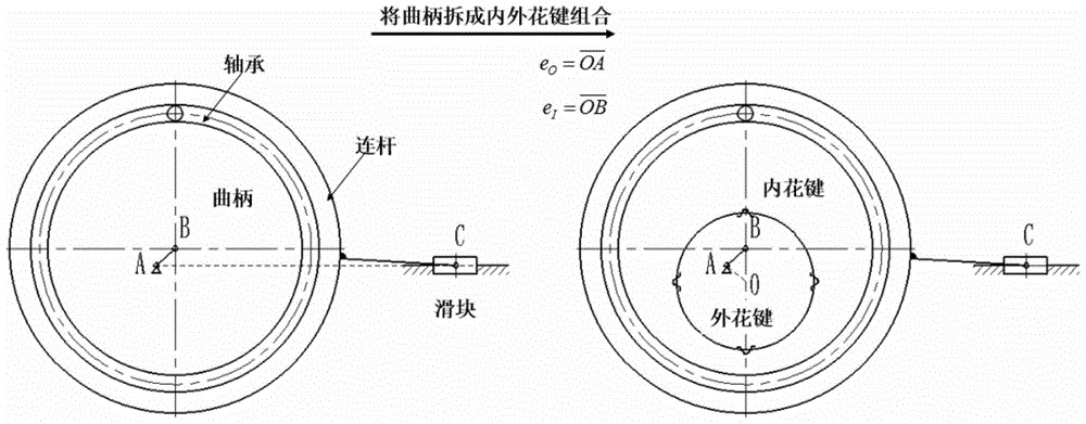
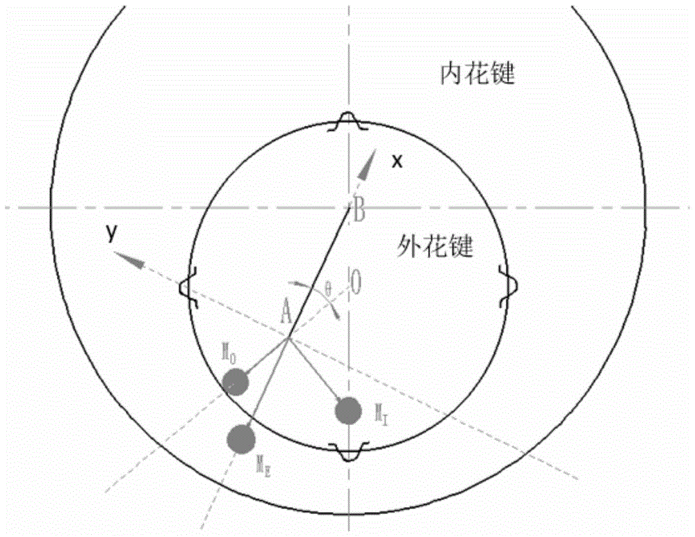
[0023] In order to obtain the crank-slider mechanism with adjustable slider stroke, the crank is disassembled into inner and outer spline combinations, such as figure 1 According to the design principle shown, each tooth of the spline rotates corresponds to a crank length, which realizes the adjustment of the crank length. Wherein O is the assembly center of the spline, A is the rotation center of the rotating pair composed of the crank and the bracket (also the rotating center of the motor shaft 1), and B is the rotating center of the rotating pair composed of the crank mechanism and the connecting rod.

[0024] The length of the crank can be expressed as:

[0025]

[0026] Then the stroke of the slider S=2l AB ∈[2|e O -e I |,2(e ...


PUM


Abstract

The invention discloses a crank-slider mechanism adjustable in stroke and capable of automatically balancing inertial force and relates to the field of mechanical transmission. The crank-slider mechanism comprises a crank mechanism and a slider mechanism which are connected with each other. An eccentric spline is adopted in the crank mechanism to cooperate with and replace a rotating pair to realize adjustability in stroke. A crank-slider structure with a crank expanded is matched with the spline, and changeable micro-amplitude reciprocating stroke of a slider is realized; by utilizing reasonable design of geometric shape and mass distribution of a spline combination, part balance of inertial force can be realized when reciprocating stroke of the crank-slider mechanism is adjusted freely. A complete designing method, a specific structure and a mass selection equation of related parts are provided for a mechanical transmission mechanism small in reciprocating stroke.

Description

technical field [0001] The invention relates to the field of mechanical transmission, in particular to a slider crank mechanism with adjustable stroke and automatic balance of inertial force. Background technique [0002] The slider crank mechanism is widely used in various fields of industry because it can convert circular motion into periodic reciprocating linear motion. For micro-reciprocating motions that require high speed and adjustable stroke (such as studying the mechanical characteristics of the sealing ring at the moment the piston is started in the reciprocating seal), the conventional crank slider structure cannot be used. However, compared with the linear mechanism of hydraulic or pneumatic transmission, the crank slider is more environmentally friendly, has stable load characteristics, and the design of the drive system is simpler, especially the high-speed characteristics are more accurate; compared with linear motors and vibrators, the crank slider mechanism ...

Claims


Application Information

Patent Timeline
Patent Type & Authority Patents(China)
IPC IPC(8): F16H21/20
CPCF16H21/20
Inventor 李坤贾晓红索双富王隆珂
Owner TSINGHUA UNIV
Learn More