Bypass regulation and control permanent magnet power device

A bypass control and power device technology, applied in the direction of electromechanical devices, electrical components, etc., can solve problems such as single function, poor load adaptability, and various types

Inactive Publication Date: 2015-08-19
林英楠
View PDF0 Cites 9 Cited by
  • Summary
  • Abstract
  • Description
  • Claims
  • Application Information

AI Technical Summary

Problems solved by technology

The above-mentioned traditional motors all have shortcomings such as low efficiency, single function, difficult speed regulation, poor load adaptability, and weak overload capa...

Method used


Image

  • Bypass regulation and control permanent magnet power device
  • Bypass regulation and control permanent magnet power device
  • Bypass regulation and control permanent magnet power device

Examples


Embodiment 1

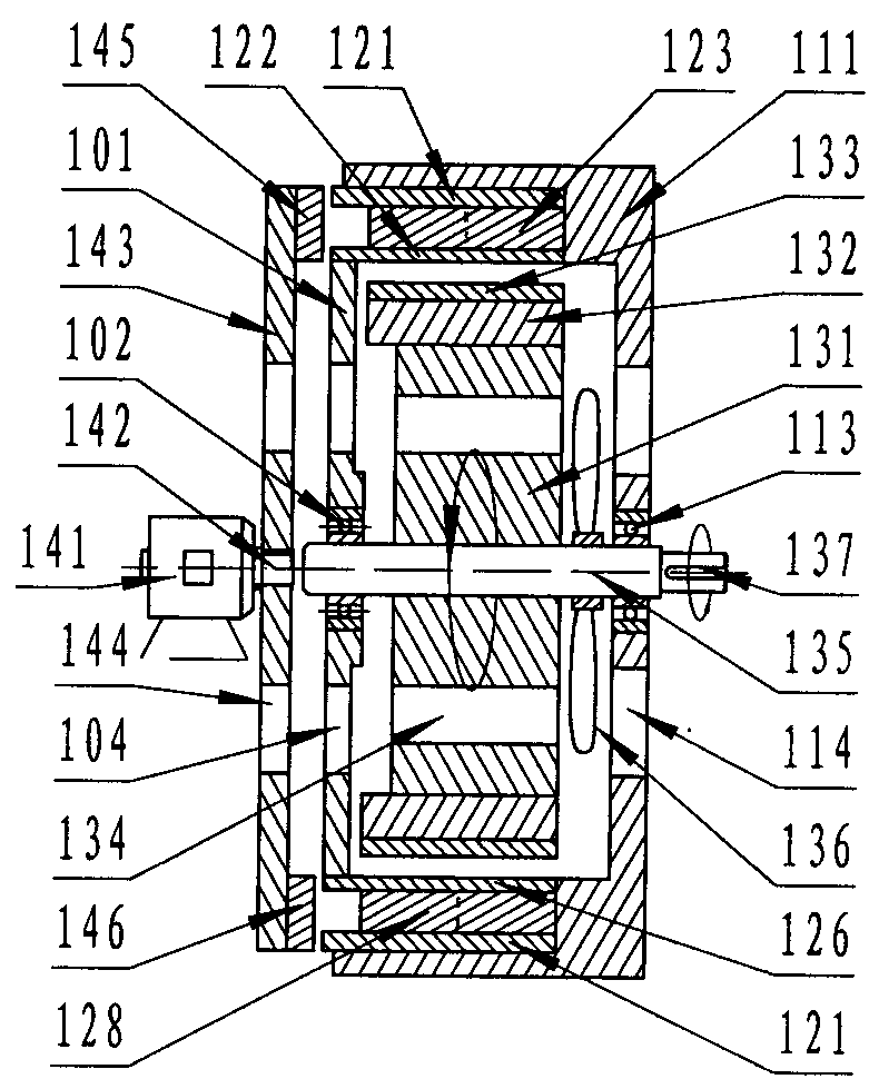
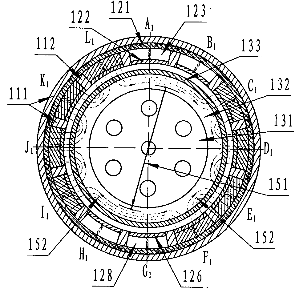
[0079] Such as Figures 1 to 8As shown, it is a bypass-regulated permanent magnet power device with a radial magnetic field air gap coupling cylindrical single-stator single-rotor structure. ), cylindrical rotors (131, 132, 133, 135), permanent magnet bypass control rotors (141, 142, 143, 145) and other accessories (102, 113, 136,), and the bypass control permanent magnet stator consists of Twelve pairs of radial magnetic field coupling bypass regulation permanent magnet assemblies (121, 123, 122) and a stator body (111); the rotor is composed of a rotor core (132), a rotor armature / rotor permanent magnet assembly (133), and the permanent The magnetic bypass control rotor is composed of bypass rotor drive components (141, 142), integrated bypass rotor (143) and bypass iron core (145), and the bypass control permanent magnet component is composed of permanent magnets (123) and magnetic shoes (121, 122), the permanent magnet in the bypass control permanent magnet assembly is se...

Embodiment 2

[0083] Such as Figures 8 to 12 As shown, it is a bypass-regulated permanent magnet power device with a radial magnetic field air gap coupled cylindrical single-stator single-rotor structure. "Layout setting, mainly controlled by the radial magnetic field coupling cylindrical bypass permanent magnet stator (211, 221, 223, 222), radial magnetic field cylindrical rotor (231, 232, 233, 235, 237), permanent magnetic bypass Regulating rotors (241, 248, 242, 243, 245) and other accessories (201, 202, 213, 236, 204, 214), radial magnetic field coupling cylindrical bypass regulating permanent magnet stators are composed of twelve sets of "H" The "H" type radial magnetic field coupling cylindrical bypass regulation permanent magnet assembly consists of permanent magnets (223) and two magnetic shoes (221, 222), the radial magnetic field cylindrical rotor (231, 232, 233, 235, 237) consists of a cylindrical rotor core / sleeve yoke (232), a cylindrical rotor armature / The rotor permanent ...

Embodiment 3

[0086] Such as Figures 13 to 16 As shown, it is a bypass-regulated permanent magnet power device with a radial magnetic field air-gap coupled cylindrical single-stator single-rotor structure. ), cylindrical rotors (331, 332, 333, 335), permanent magnet bypass control rotors (341, 342, 343, 345) and other accessories (302, 313, 336,), it is different from Embodiment 1 The location is: ①The stator is evenly distributed with six sets of "I" type bypass control permanent magnet assemblies A 2 , B 2 ... and F3; 2. The permanent magnets (323, 328) in the bypass regulation permanent magnet assembly are combined permanent magnets; 3. The size of the bypass iron core (345, 346) arranged on the bypass rotor (343) is relatively small Small, corresponding to the construction of a bypass magnetic circuit in a bypass regulating permanent magnet assembly. The working mechanism of this embodiment is similar to Embodiment 1, and will not be repeated here.


PUM


Abstract

The invention discloses a bypass regulation and control permanent magnet power device, and the device mainly consists of a bypass regulation and control permanent magnet stator, a rotor, a permanent magnet bypass regulation and control rotor, and other accessories. The bypass regulation and control permanent magnet stator consists of at least one pair of bypass regulation and control permanent magnet assemblies and a stator body. The permanent magnet bypass regulation and control rotor consists of a bypass rotor drive assembly, an integrated bypass rotor, and a bypass iron core. Each of bypass regulation and control permanent magnet assemblies consists of a permanent magnet and a magnetic boot, and the permanent magnets of the bypass regulation and control permanent magnet assemblies are disposed between the two magnetic boots or between the magnetic boots and a magnet yoke. One end of each magnetic boot is a permanent magnet bypass end, and the other end of each magnetic boot is provided with a magnetic boot coupling surface which is used for building a 'bypass regulation and control permanent magnet stator-rotor' air-gap coupling magnetic circuit. The device is high in efficiency, achieves stepless speed control, is high in load adaptability, can provide green power and energy for all industries, and is great in market prospect.

Description

technical field [0001] The technical fields involved in the present invention include: the technical field of power equipment, the technical field of energy, especially a permanent magnet power device for bypass regulation, which includes a bypass regulation cylinder type magnetodynamic device, a bypass regulation disc type magnetodynamic device, a bypass regulation The combination of the path regulating drum and disk / composite magnetic power device and the linear (displacement) bypass regulating magnetic power device. Background technique [0002] In the familiar industrial and agricultural production and daily life of various equipment, there are countless examples of using electric motors or internal combustion engines as power drives, and equipment that can output power is the basis of various human lives. Various electric motors or internal combustion engines within the scope consume most of the world's existing energy production capacity, but with the massive consumpti...

Claims


Application Information

Patent Timeline
IPC IPC(8): H02K16/02
Inventor 王忠勇余增涛高志宏林英楠其他发明人请求不公开姓名
Owner 林英楠
Why Eureka
Try Eureka