System for continuous manufacture of optical display panels, and method for continuous manufacture of optical display panels
A technology for optical display panels and manufacturing systems, applied in chemical instruments and methods, optics, optical components, etc., can solve problems such as bubbles in optical films and liquid crystal units
- Summary
- Abstract
- Description
- Claims
- Application Information
AI Technical Summary
Problems solved by technology
Method used
Image

Examples
Embodiment approach 1
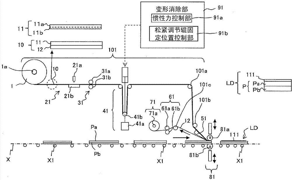
[0085] figure 1 is a simplified diagram of a continuous manufacturing system for optical display panels. Below, refer to figure 1 The continuous manufacturing system of the optical display panel which concerns on this embodiment is demonstrated concretely.
[0086] In addition, in this embodiment, the example of the rectangular liquid crystal cell is mentioned as an optical cell, and the example of a rectangular liquid crystal display panel is mentioned and demonstrated as an optical display panel. As an optical film roll, usefigure 1 components shown. That is, as the optical film roll 1, a member wound with a strip-shaped laminated optical film 10 formed by laminating a strip-shaped laminated optical film 10 having an absorption axis in the longitudinal direction on a carrier film 12 is used. The polarizing film 11 (corresponding to an optical film) has a width corresponding to the long side of the liquid crystal cell P. As shown in FIG. In addition, in this embodiment, t...
Embodiment approach 2
[0124] Embodiment 2 has the same functions as those of Embodiment 1 described above, and a configuration specific to Embodiment 2 will be described below.
[0125] In order to reduce or eliminate (substantially eliminate) the vibration generated when the dancer roller 41b operates, the deformation canceling unit 91 of the second embodiment controls to operate while braking the dancer roller 41b. Thereby, generation|occurrence|production of air bubbles at the initial stage of bonding can be suppressed.
[0126]
[0127] use figure 1 The following examples 1 to 6 were carried out in a continuous production system. use figure 1 In the production system shown, a polarizing film (VEGQ1724DU manufactured by Nitto Denko Co., Ltd.) was bonded to a liquid crystal cell (40-inch size).
[0128] In Examples 1 to 6 and Comparative Examples 1 to 3, as shown in Table 1, the thickness of the laminated optical film, the film feeding (transportation) speeds of the inner feed roller part, t...
Embodiment 1
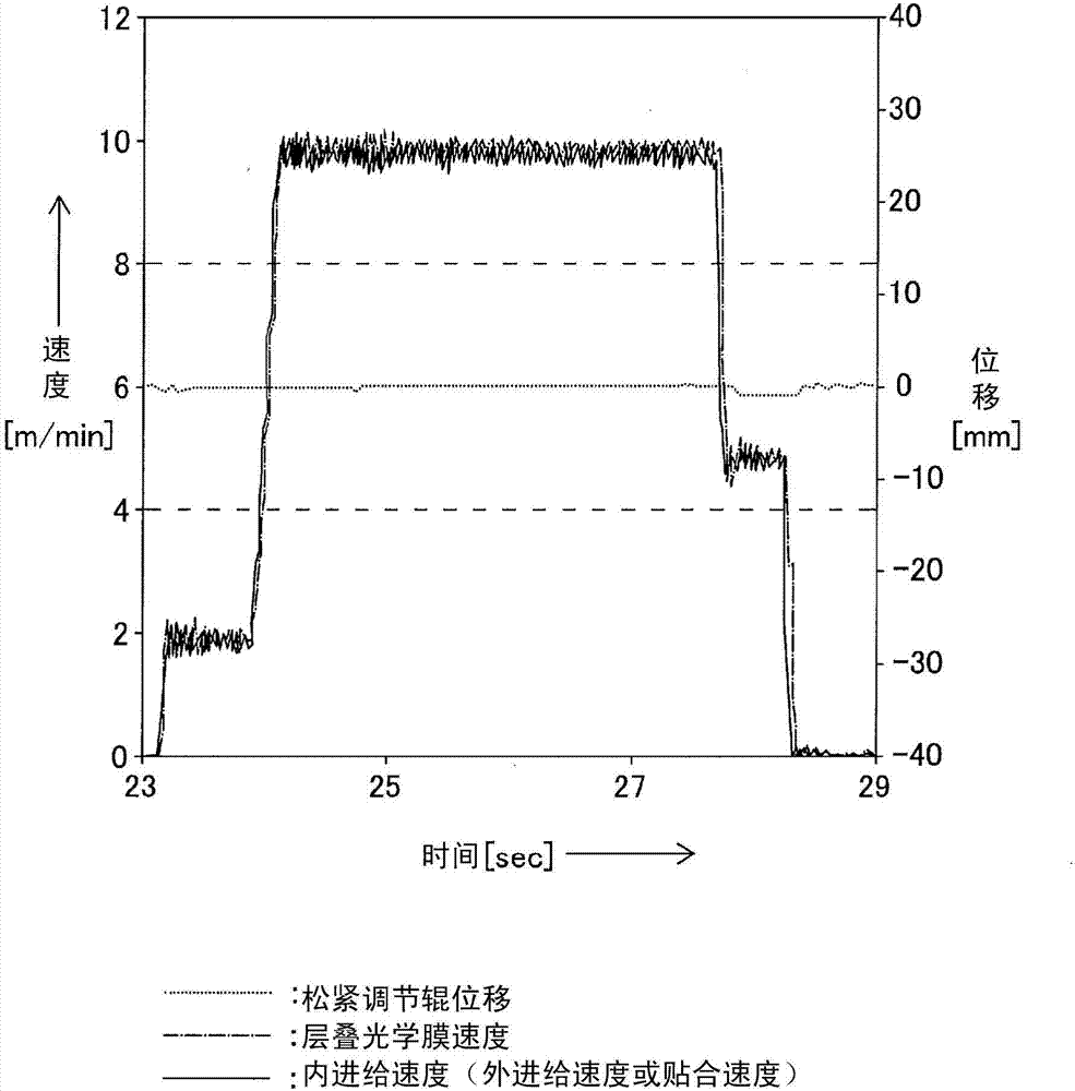
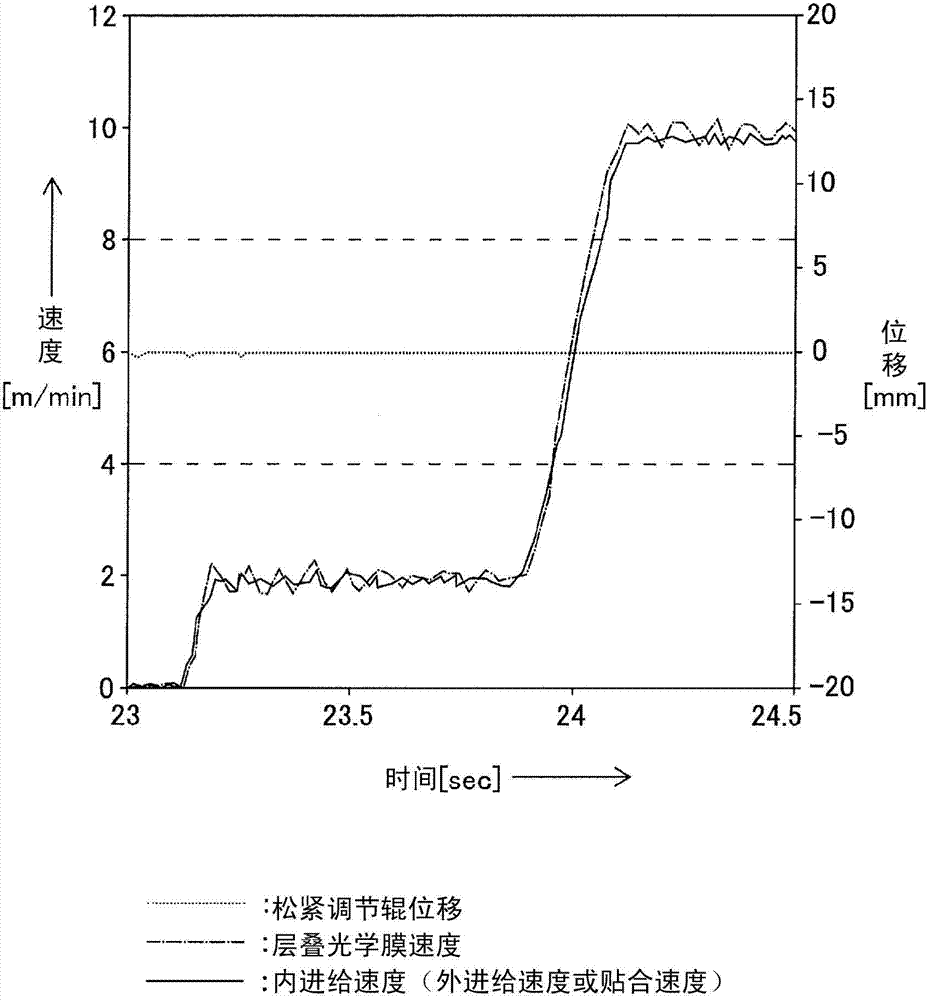
[0131] In Example 1, the inner feed speed, the outer feed speed, and the bonding speed are all synchronized and controlled so that the dancer roller does not move (does not move) at the same speed, thereby changing the speed of the laminated optical film. Small. Therefore, generation of bubbles was not observed. Figure 2A In Example 1, the internal feed speed (same as the external feed speed or bonding speed), the speed of the laminated optical film, and the speed of the dancer roll during the bonding period of the polarizing film to the liquid crystal cell are shown. displacement. Figure 2B yes Figure 2A An enlarged view of the early stage of the drive.
PUM
| Property | Measurement | Unit |
|---|---|---|
| thickness | aaaaa | aaaaa |
| thickness | aaaaa | aaaaa |
| thickness | aaaaa | aaaaa |
Abstract
Description
Claims
Application Information
 - R&D Engineer
- R&D Manager
- IP Professional
- Industry Leading Data Capabilities
- Powerful AI technology
- Patent DNA Extraction
Browse by: Latest US Patents, China's latest patents, Technical Efficacy Thesaurus, Application Domain, Technology Topic.
© 2024 PatSnap. All rights reserved.Legal|Privacy policy|Modern Slavery Act Transparency Statement|Sitemap