An indoor positioning method and device

An indoor positioning and positioning point technology, applied in wireless communication, electrical components, etc., can solve problems such as increased computing overhead, large signal strength fluctuations, and inaccurate positioning, so as to improve the positioning experience and reduce the amount of matching calculations.

Active Publication Date: 2018-11-09
RUIJIE NETWORKS CO LTD
View PDF2 Cites 0 Cited by
  • Summary
  • Abstract
  • Description
  • Claims
  • Application Information

AI Technical Summary

Problems solved by technology

[0006] However, when the above-mentioned fingerprint positioning scheme increases the indoor area, it needs to traverse more sampling points to calculate the similarity, which increases the computational overhead
In addition, when the actual terminal is positioned, it is often in a moving state. If the signal strength fluctuates greatly, or the terminal moves faster, the positioning result is often a set of discrete points with large jumps, and the positioning effect is not ideal.
[0007] Whether it is a ranging method or a non-ranging method, the effect of indoor positioning is not optimized enough, and the positioning is not accurate enough

Method used


Image

  • An indoor positioning method and device
  • An indoor positioning method and device
  • An indoor positioning method and device

Examples


Embodiment 1

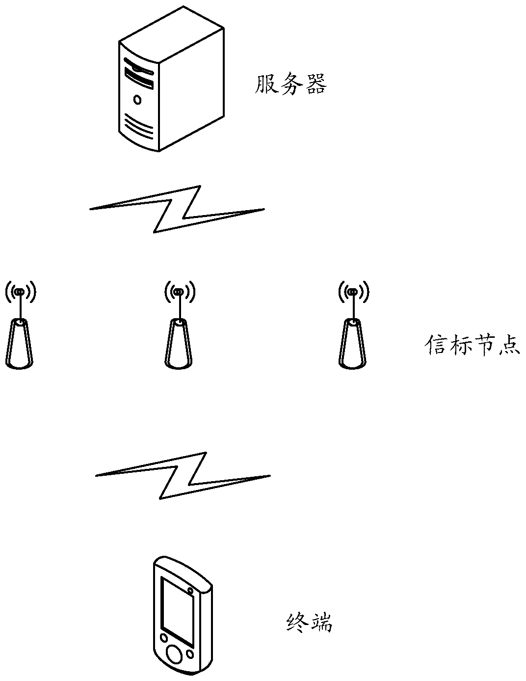
[0059] In this embodiment, the positioning area needs to be calibrated in advance, and beacon nodes are arranged in the positioning area as required, so as to at least ensure that each position requiring positioning can receive 3 or more signals. And record the attributes of each beacon node, which include: MAC, transmit power, location information, etc. Subsequent positioning needs to be used to determine the beacon node: location information, MAC; use the rasterization device to rasterize the area to be positioned to obtain grid points. In this embodiment, the upper left corner vertex of each grid is selected as the coordinates of the grid Point to rasterize the area to be positioned;

[0060] In this embodiment, it is also necessary to set up a fingerprint database for the area to be positioned in advance. What the fingerprint database reflects is the fingerprint corresponding to each grid point in the area to be positioned. The fingerprint refers to: the corresponding rela...

Embodiment 2

[0130] This embodiment provides an indoor positioning device, and its specific implementation structure is as follows Figure 5 As shown, specifically, the following modules may be included: a determination module 21, an acquisition module 22 and a positioning module 23, wherein,

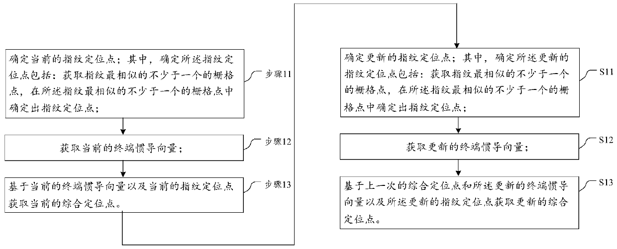
[0131] Determination module 21: it is used to determine the current fingerprint anchor point; wherein, determining the fingerprint anchor point includes: obtaining no less than one grid point with the most similar fingerprint, and no less than one grid point with the most similar fingerprint Determine the fingerprint positioning point in the grid point;

[0132] Obtaining module 22: it is used to obtain the current terminal inertial vector;

[0133] Positioning module 23: it acquires the current integrated positioning point based on the current terminal inertial vector and the current fingerprint positioning point.

[0134] An indoor positioning device of the present invention also includes:

[0...


PUM


Abstract

The invention provides an indoor positioning method and device. The method comprises that a present fingerprint positioning point is determined by obtaining at least one grid point most similar to the fingerprint, and determining the fingerprint positioning point among the at least one grid point; a present inertial navigation vector of a terminal is obtained; and a present comprehensive positioning point is obtained based on the present inertial navigation vector of the terminal and the present fingerprint positioning point. Beacon nodes are ordered according to the intensity of receives signals during positioning calculation, fingerprint is coupled at sampling points near the N beacon nodes of the highest intensity, and the calculation amount of coupling is reduced. Preset inertial navigation is combined with the fingerprint positioning result in terminal equipment to improve the user experience.

Description

technical field [0001] The present invention relates to the field of indoor positioning, in particular to an indoor positioning method and device. Background technique [0002] Indoor positioning is a hotspot in the research of positioning technology. Most of the existing indoor positioning technologies are based on existing indoor WSN (wireless Sensor Network, wireless sensor network), such as ZigBee, beacon, or WLAN (WirelessLocal Area Networks, wireless local area network) networks. The hardware device is positioned by adding software. [0003] Existing indoor positioning solutions are divided into: ranging and non-ranging; [0004] Ranging methods, such as three-point positioning: use the received signal strength RSSI (Received Signal Strength Indication) or deduce the distance according to the electromagnetic wave attenuation model. The former requires nanosecond-level clock synchronization, while the latter RSSI is affected by indoor complex environments, such as mul...

Claims


Application Information

Patent Timeline
Patent Type & Authority Patents(China)
IPC IPC(8): H04W64/00
CPCH04W64/006
Inventor 李熙
Owner RUIJIE NETWORKS CO LTD
Why Eureka
Try Eureka