Layered lens array, production method for layered lens array, and production method for layered lens
A lens array and manufacturing method technology, applied in the direction of lenses, instruments, applications, etc., can solve the problems of increased working hours, outflow of defective products, and increased adjustment times.
- Summary
- Abstract
- Description
- Claims
- Application Information
AI Technical Summary
Problems solved by technology
Method used
Image

Examples
no. 1 Embodiment approach 〕
[0041] A) Laminated lens array
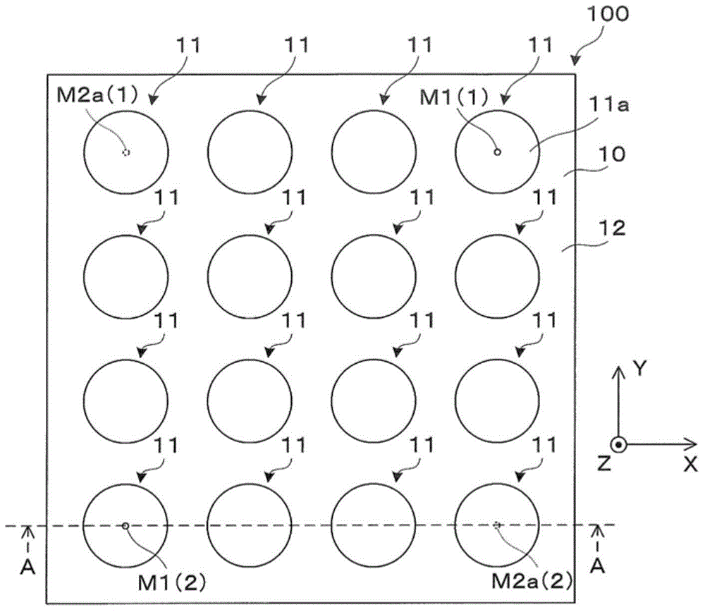
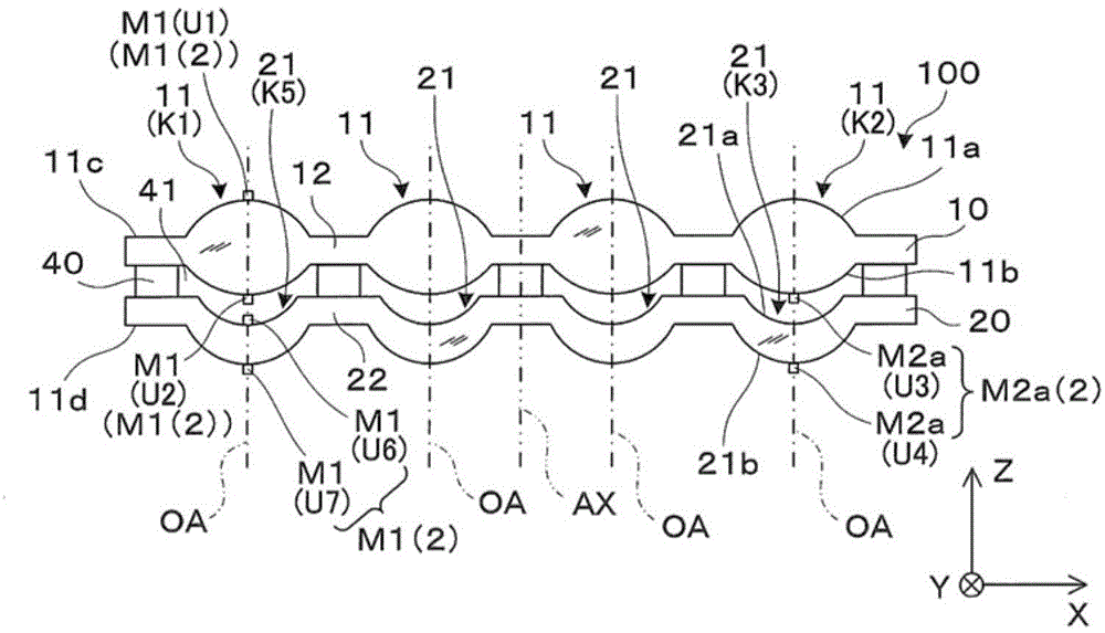
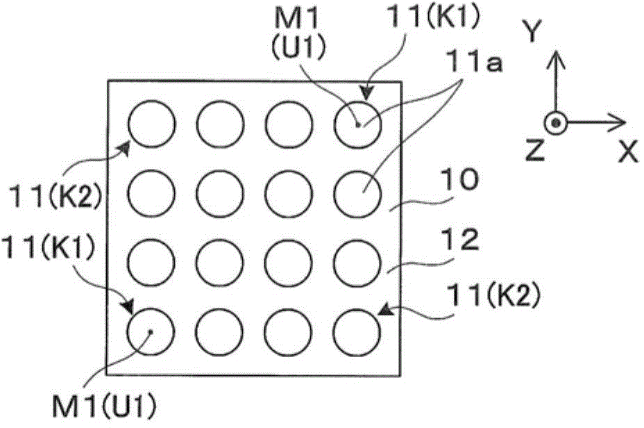
[0042] refer to Figure 1A , 1B and 2A to 2D describe the laminated lens array according to the first embodiment of the present invention. in addition, Figure 2A-2D It is a diagram illustrating the arrangement of the first to fourth, sixth and seventh marks U1 to U4, U6, and U7 on each optical surface 11a, 11b, 21a, and 21b. Arrangement of the first to fourth, sixth and seventh marks U1 to U4, U6, and U7 viewed from the surface 11a side.
[0043] Such as Figure 1A and 1B As shown, the laminated lens array 100 has, for example, a rectangular shape, and has a first lens array 10 , a second lens array 20 , and a spacer substrate 40 .
[0044] The first lens array 10 is made of glass, and has a plurality of lens portions 11 and a support body 12 connected to the plurality of lens portions 11 . The first lens array 10 is a plate-shaped member provided with a plurality of lens shapes when viewed macroscopically.
[0045] The respective lens po...
no. 2 Embodiment approach 〕
[0096] Hereinafter, the laminated lens array etc. which concern on 2nd Embodiment are demonstrated. In addition, the laminated lens array etc. of 2nd Embodiment are formed by deform|transforming the laminated lens array etc. of 1st Embodiment, and the part which is not demonstrated especially is the same part as 1st Embodiment.
[0097] Such as Figure 10 As shown, the first and second pairs of marks M1, M2a are respectively arranged at two positions along the side length direction. That is, the lens portions 11, 21 on the column L1 of the lens portions 11, 21 arranged in a matrix form are provided with the first, second, sixth and seventh marks U1, U2, U6 as the first pair of marks M1. , U7, the lens parts 11, 21 on the column L2 are provided with the third and fourth marks U3, U4 as the second pair of marks M2a. Thereby, it becomes easy to intuitively understand the direction of the rotational displacement of the 1st and 2nd lens array 10,20, Therefore The adjustment of ec...
no. 3 Embodiment approach 〕
[0099] Hereinafter, the laminated lens array etc. which concern on 3rd Embodiment are demonstrated. In addition, the laminated lens array etc. of 3rd Embodiment are formed by deform|transforming the laminated lens array etc. of 1st Embodiment, and the part which is not demonstrated especially is the same part as 1st Embodiment.
[0100] Such as Figure 11A As shown, the laminated lens array 300 has a first lens array 10 , a second lens array 20 , a third lens array 30 , and spacer substrates 40 and 50 . That is, the laminated lens array 300 is composed of three lens arrays.
[0101]The first and second lens arrays 10 and 20 and the spacer substrate 40 are the same as those of the first embodiment.
[0102] The structure of the third lens array 30 is substantially the same as that of the first lens array 10 , so the description thereof will be appropriately omitted below. The third lens array 30 is made of glass or resin, and has a plurality of lens units 31 and a support bo...
PUM
 Abstract
Description
Claims
Application Information
 - R&D
- Intellectual Property
- Life Sciences
- Materials
- Tech Scout
- Unparalleled Data Quality
- Higher Quality Content
- 60% Fewer Hallucinations
Browse by: Latest US Patents, China's latest patents, Technical Efficacy Thesaurus, Application Domain, Technology Topic, Popular Technical Reports.
© 2025 PatSnap. All rights reserved.Legal|Privacy policy|Modern Slavery Act Transparency Statement|Sitemap|About US| Contact US: help@patsnap.com