Optical tracking device using micromirror array lenses

a technology of optical tracking and micromirror array, which is applied in the field of optical tracking devices, can solve the problems of large package, high cost and slow response, and the inability of optical tracking devices with single cameras to produce three-dimensional image information, and achieves the effect of simple optical tracking devices, large tracking area, and quick change of effective focal length of lens units

Active Publication Date: 2008-11-06
STEREO DISPLAY
View PDF5 Cites 90 Cited by
  • Summary
  • Abstract
  • Description
  • Claims
  • Application Information

AI Technical Summary

Benefits of technology

[0041]The method for tracking the target using an optical tracking device further comprises measuring the distance between the lens unit and the target by extracting an in-focus target image from the scene image using the image processing unit. The method for tracking the target using an optical device further comprises measuring three-dimensional image information of the target by changing a focal plane of the lens unit by adjusting the effect focal length of the lens unit. The method for tracking a target using an optical tracking device further comprises using a time-sharing technique to obtain a wide field of view image and a narrow field of view image within a short time period.
[0042]The optical tracking device of the present invention has many advantages. The optical tracking device w

Problems solved by technology

However, it comes with high cost and slow response due to pixel to pixel charge transfer and tends to result in a large package because the control circuitry cannot be integrated into an image sensor.
However, the optical tracking device with the single camera cannot produce three-dimensional image information.
Furthermore, it is difficult to extract distance information from the single camera unless it is used in combination with a device such as a range finder.
Additionally, it is easy to lose track of fast moving targets because a field of view (FOV) of the single camera is limited.
Therefore, the imaging system with the single camera typical

Method used


Image

  • Optical tracking device using micromirror array lenses
  • Optical tracking device using micromirror array lenses
  • Optical tracking device using micromirror array lenses

Examples


Embodiment Construction

[0064]The present invention will now be described in detail with reference to embodiments thereof as illustrated in the accompanying drawings. In the following description, numerous specific details are set forth in order to provide a thorough understanding of the present invention. It will be apparent, however, to one skilled in the art, that the present invention may be practiced without some or all of these specific details. In other instances, well known process steps and / or structures have not been described in detail in order to not unnecessarily obscure the present invention.

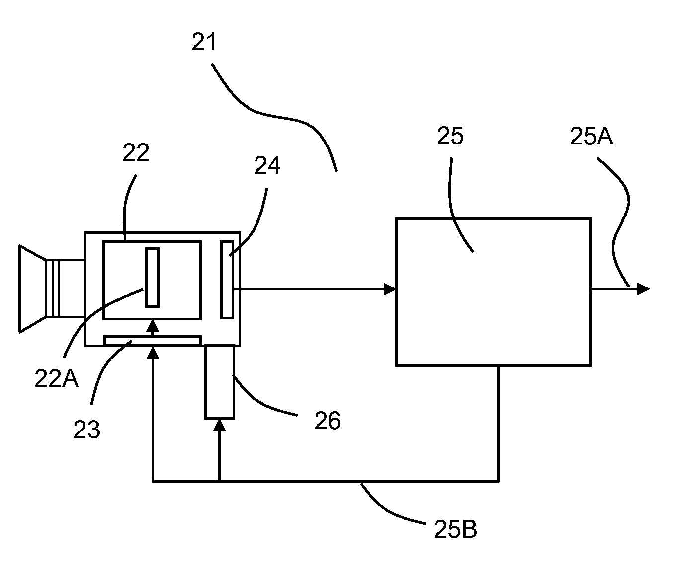
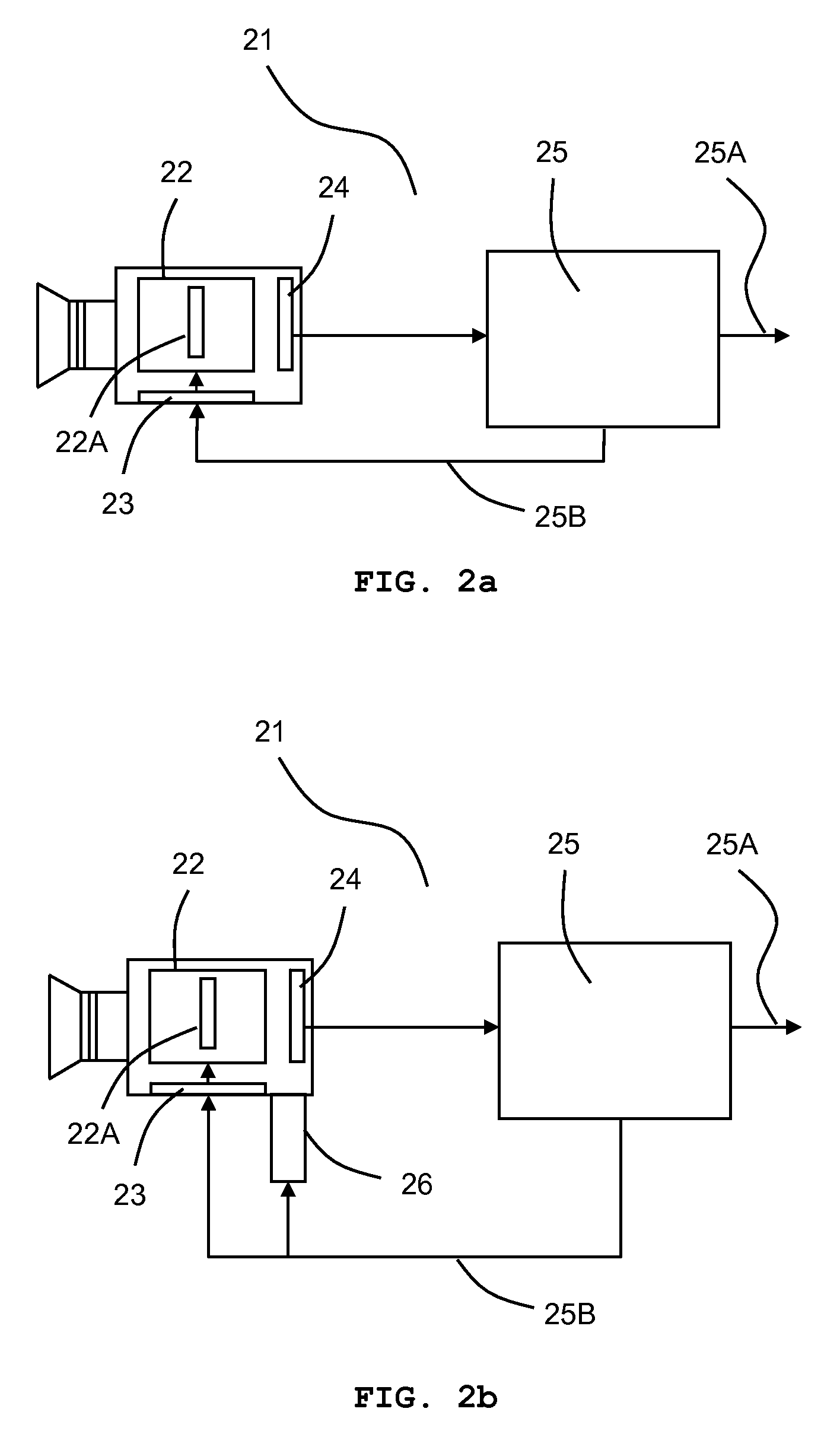
[0065]FIGS. 2 (2a˜2b) are block diagrams of optical tracking devices according to the embodiments of the present invention. In one embodiment depicted in FIG. 2a, the optical tracking device 21 of this invention comprises a lens unit 22, a control circuitry 23 communicatively coupled to the lens unit 22, and an imaging unit, comprising at least one image sensor 24, optically coupled to the lens unit 22. T...


PUM


Abstract

The optical tracking device of this invention comprises a lens unit, a control circuitry communicatively coupled to the lens unit, and an imaging unit optically coupled to the lens unit. The lens unit comprises at least one Micromirror Array Lens, wherein the Micromirror Array Lens comprises a plurality of micromirrors and is configured to have a plurality of optical surface profiles by controlling rotations or translations of the micromirrors. The optical tracking device of the invention further comprises an image processing unit, communicatively coupled to the imaging unit, configured to process the image information from the imaging unit and generates a control signal for the control circuit to control the lens unit. The optical tracking device of the present invention provides capability of tracking a target moving in a high speed, providing three-dimensional image information of the object, and compensating the aberration of the optical tracking device.

Description

FIELD OF THE INVENTION[0001]The present invention relates to optical devices in general, and more specifically to an optical tracking device.BACKGROUND OF THE INVENTION[0002]Tracking systems have numerous applications, including those detailed in the following patents; autonomous vehicles (U.S. Pat. No. 6,535,114), monitoring systems (U.S. Pat. No. 6,690,374), sports cameras (U.S. Pat. No. 6,567,038), conference video systems (U.S. Pat. No. 6,507,366), surgery (U.S. Pat. Nos. 6,725,079 and 6,662,036), positioning (U.S. Pat. No. 6,490,473), inspection (U.S. Pat. No. 6,259,960), spotlighting (U.S. Pat. No. 6,079,862), and machining (U.S. Pat. No. 6,429,404). Tracking systems use certain distinguishing features of a target being tracked as sources for detecting, tracking, or engaging the target. These features can be any form of energy emitted or reflected from the target including radio, millimeter-wave, infrared, visible light, laser, ultraviolet, and sound. Each energy source has di...

Claims


Application Information

Patent Timeline
IPC IPC(8): G01C3/08G01P3/36
CPCG01C3/08G01S3/7864G01S11/12H04N5/2254H04N5/232H04N23/60H04N23/55
Inventor KIM, HYE YOUNGSOHN, JIN YOUNGCHO, GYOUNG ILSEO, CHEONG SOO
Owner STEREO DISPLAY
Why Eureka
Try Eureka