Horizontal circulating type dust collector

A circulating flow, dust collector technology, applied in chemical instruments and methods, separation methods, dispersed particle separation, etc., can solve the problems of inability to reduce noise, large pressure loss in the air flow path, long fluid flow path, etc., to optimize the dust removal effect. and efficiency, overcoming the effect of dust removal efficiency, overcoming the effect of long flow path

Inactive Publication Date: 2015-09-02
QINGDAO UNIV OF SCI & TECH
View PDF5 Cites 1 Cited by
  • Summary
  • Abstract
  • Description
  • Claims
  • Application Information

AI Technical Summary

Problems solved by technology

[0004] Obviously, the traditional cyclone dust collector has the following defects: ①The whirling path of the dust flowing into the interior is too long, so the contact time of the dust with the inner wall of the dust collector body is too long during the whirling down process, so the noise cannot be reduced; ②The air flow path Too long will lead to excessive pressure loss; ③ All kinds of dust enter the interior of the ash storage hopper with residual whirling force, which will cause the dust already collected in the ash storage hopper to generate secondary dust, thus reducing the dust collection efficiency
[0005] These defects eventually lead to the disadvantages of long fluid flow path and large velocity gradient in the traditional cyclone dust collector, so the pressure drop is large, the energy consumption is high, the operation stability is poor, and the amplification effect is significant.
In addition, due to its own structural design, the traditional cyclone dust collector must have an upper vortex near the inlet of the exhaust pipe (some people call it a short-circuit flow).
Research analysis shows that due to the existence of the upper vortex, some dust particles return to the clean air flow and are taken out of the cyclone dust collector, which is the basic reason for the low dust removal efficiency of the traditional cyclone dust collector

Method used


Image

  • Horizontal circulating type dust collector
  • Horizontal circulating type dust collector
  • Horizontal circulating type dust collector

Examples


Embodiment Construction

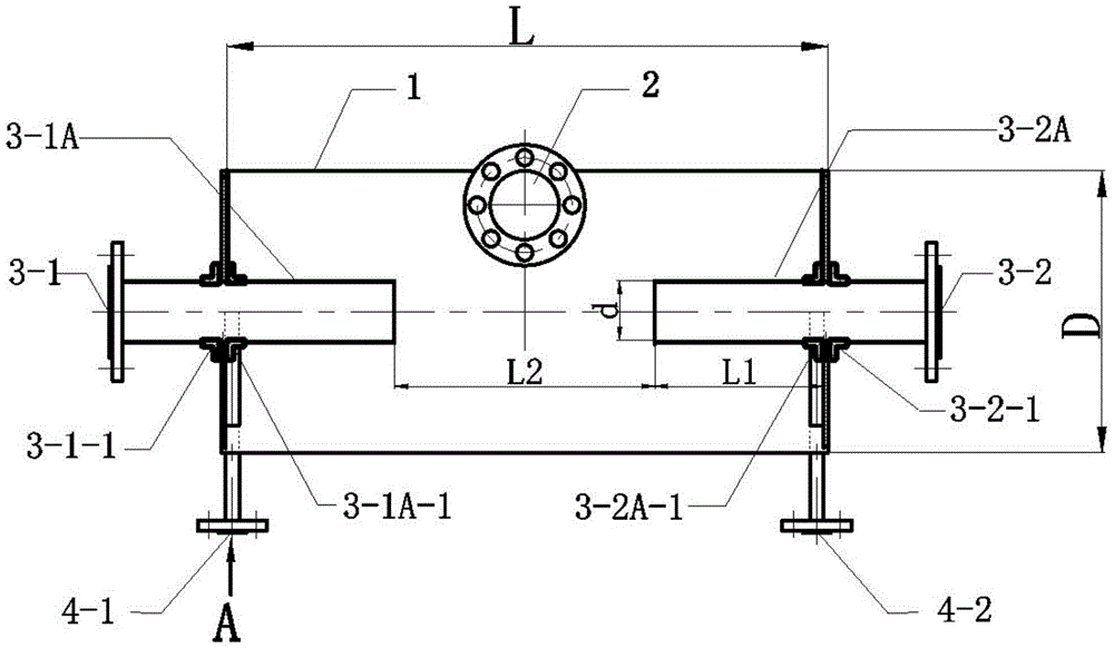
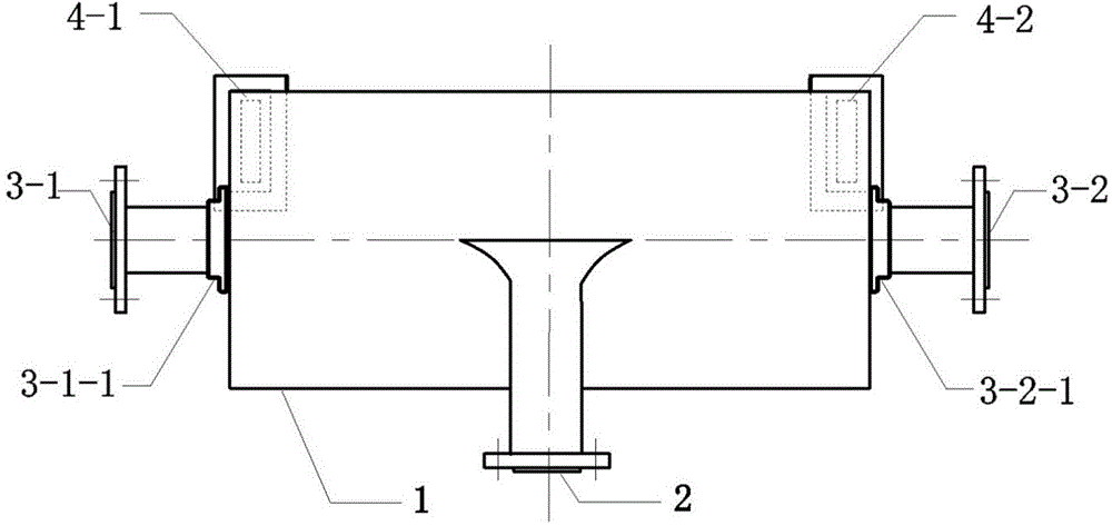
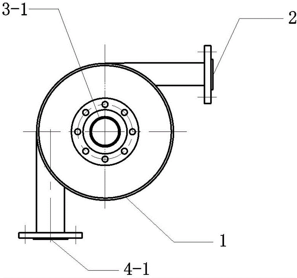
[0018] Describe the implementation process of the present invention in detail in conjunction with accompanying drawing, as figure 1 , figure 2 , image 3 , Figure 4 Shown, the present invention is by cylindrical body 1, air inlet pipe mouth 2, two clean gas exhaust pipe mouths 3-1, 3-2, two dust separation pipes 3-1A, 3-2A, two rectangular row The dust pipe mouth 4-1, 4-2 forms. The cylinder body 1 is arranged horizontally, and the two ends of the cylinder body 1 are sealed by sealing end caps; the air inlet pipe opening 2 is arranged at the upper part of the cylinder body 1 and connected tangentially with the cylinder body; two clean gas exhaust pipe openings 3 -1, 3-2, through the flange 3-1-1 and the flange 3-2-1, respectively, installed on the outside of the center of the sealing end cover at both ends of the cylinder 1; two dust separation pipes 3 -1A, 3-2A, through the flange 3-1A-1 and the flange 3-2A-1, are coaxial with the clean gas exhaust pipe ports 3-1, 3-2 a...


PUM


Abstract

The invention relates to dust removal devices, in particular to a horizontal circulating type dust collector. The horizontal circulating type dust collector comprises a cylinder, an air inlet pipe port, two clean air exhaust pipe ports, two dust separating pipes and two rectangular dust exhaust pipe ports. The cylinder is horizontally arranged with two ends sealed by sealing end caps, the air inlet pipe port is arranged above the middle of the cylinder and is tangentially connected with the cylinder, the clean air exhaust pipe ports are arranged in the outer sides of the sealing end caps at two ends of the cylinder respectively, the dust separating pipes are arranged on the inner sides of the sealing end caps respectively, the rectangular dust exhaust pipe ports are downwardly mounted at two ends of the cylinder tangentially and perpendicularly, and the air inlet pipe port, the clean air exhaust pipe ports and the rectangular dust exhaust pipe ports are connected with a pipeline system. The horizontal circulating type dust collector overcomes the defects that a conventional cyclone dust collector is long in flowing route, high in pressure drop and energy consumption, low in operation flexibility and remarkable in amplification effect and the like and effectively eliminates influences on dust collection efficiency from short-circuit current and upper vortex in the cyclone dust collector.

Description

1. Technical field [0001] The invention relates to dust collector equipment, in particular to a horizontal circulation dust collector. 2. Background technology [0002] The traditional cyclone dust collector is a vertical structure, which uses the principle of the circulation of the dust-laden gas inside the dust collector and the principle of the dust itself being affected by gravity to separate the dust from the high-speed airflow and discharge the clean gas to the outside. [0003] The traditional cyclone dust collector consists of an inlet pipe, an exhaust pipe, a cylinder, a cone and an ash hopper. When the cyclone dust collector starts to work, the dusty gas from the outside is sent to the interior of the dust collector body through the air inlet by the fan. Under the action of the wind pressure, the dusty gas whirls down along the inner wall of the dust collector body. The dust separated by the cyclone dust collector is discharged through the dust outlet located unde...

Claims


Application Information

Patent Timeline
IPC IPC(8): B01D45/16
Inventor 郭建章蒋骏
Owner QINGDAO UNIV OF SCI & TECH
Why Eureka
Try Eureka