Adjustable gear-hob cutting force measurement device

A technology of gear hobbing cutting force and measuring device, which is applied to measuring devices, force/torque/work measuring instruments, instruments, etc., can solve the problems of inconvenient installation of gear workpieces, inconvenient cutting force data analysis, affecting the measurement accuracy of instruments, etc. Achieve the effect of short measurement preparation time, good rigidity and improved measurement accuracy

Inactive Publication Date: 2015-09-02
TIANJIN UNIV OF COMMERCE
View PDF6 Cites 4 Cited by
  • Summary
  • Abstract
  • Description
  • Claims
  • Application Information

AI Technical Summary

Problems solved by technology

[0003] Usually the hobbing cutting force is indirectly estimated by observing the current fluctuation of the hob spindle motor, the result is inaccurate, there is a time lag, and it is not convenient for data analysis of cutting force
However, the cutting force of hobbing is directly measured by the cutting dynamometer, because the gear workpiece is not convenient to be directly installed on the platform of the cutting dynamometer, and a large amount of cutting oil will seep into the interface of the cable and the internal sensor, affecting the measurement accuracy of the instrument

Method used


Image

  • Adjustable gear-hob cutting force measurement device
  • Adjustable gear-hob cutting force measurement device
  • Adjustable gear-hob cutting force measurement device

Examples


Embodiment Construction

[0020] The present invention will be described in further detail below in conjunction with the accompanying drawings and specific embodiments.

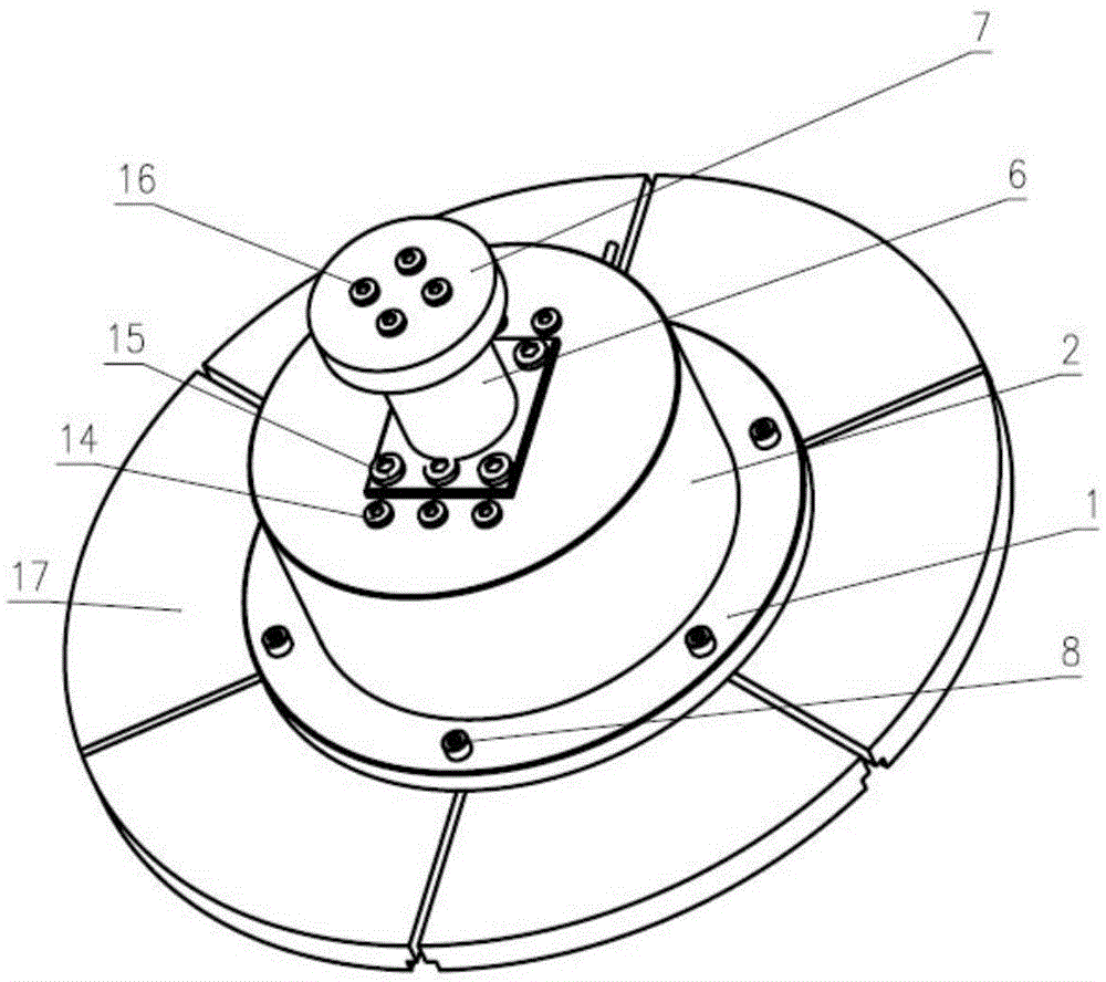
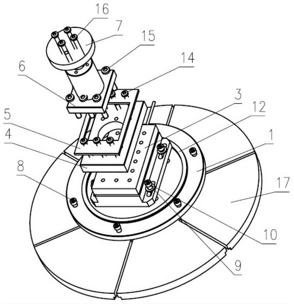
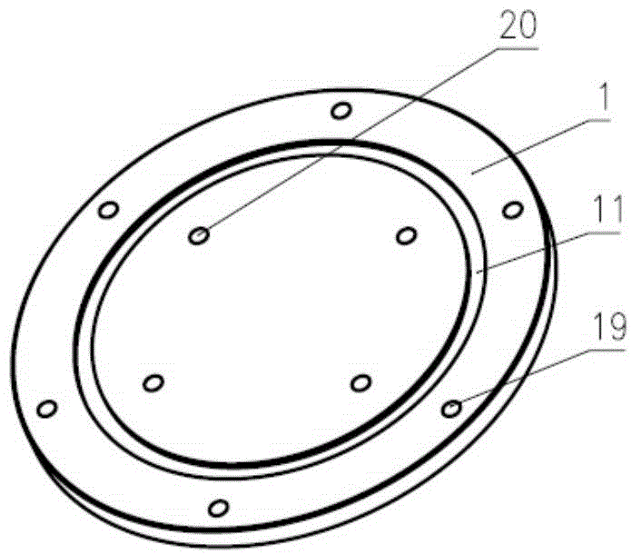
[0021] The schematic diagram of an adjustable hobbing force measuring device of the present invention is as follows Figure 1-Figure 8 As shown, it includes a bottom fixed plate 1, a cutting dynamometer 3, a top fixed plate 4, a sealing cover 2, a support mechanism and a square sealing ring 5, the bottom fixed plate 1 is circular, and the bottom fixed plate 1 is provided with There are circular grooves 11. The bottom of the cutting dynamometer 3 is fixedly connected to the bottom fixing plate 1 through a screw 9 and a washer 10 passing through a hole 20 . The top of the cutting dynamometer is provided with a top fixing plate 4 . Described support mechanism comprises positioning round platform 29, square platform 28 and support column 6, and described top fixed plate 4 is provided with the mounting hole 25 that matches with described...


PUM


Abstract

The invention discloses an adjustable gear-hob cutting force measurement device, and the device is simple in structure, is convenient and practical, and is high in precision. The bottom of a cutting force measurement instrument is fixedly connected with a bottom fixed plate. The top of the cutting force measurement instrument is provided with a top fixed plate. The supporting mechanism comprises a positioning truncated cone, a square platform, and a supporting column, wherein the positioning truncated cone is installed in an installation hole. The supporting column is provided with a workpiece installation hole and a fixed hole. A sealing cover consists of a side enclosing plate and a top plate, which are integrated into a body. The top plate is provided with a square hole corresponding to the square platform. A square sealing ring is placed between the top plate and the top fixed plate. The side enclosing plate encloses the square sealing ring, the top fixed plate and the cutting force measurement instrument. The bottom of the side enclosing plate is provided with a connection hole, and is disposed in a circular groove in a sealed manner through a circular sealing ring. The square platform, the top fixed plate and the top of the cutting force measurement instrument are in fixed connection. The top plate of the sealing cover, the square sealing ring and the top fixed plate are in fixed connection. The device is simple in structure and is accurate in measurement.

Description

technical field [0001] The invention relates to the technical field of cutting, and more specifically relates to an adjustable hobbing cutting force measuring device. Background technique [0002] In order to study the technological parameters of gear hobbing and improve the efficiency of gear hobbing, it is necessary to measure the dynamic cutting force during hob machining in real time. [0003] Usually the hobbing cutting force is indirectly estimated by observing the current fluctuation of the hob spindle motor, the result is inaccurate, there is a time lag, and it is not convenient to analyze the cutting force data. However, the cutting force of hobbing is directly measured by the cutting dynamometer, because the gear workpiece is not convenient to be directly installed on the platform of the cutting dynamometer, and a large amount of cutting oil will seep into the interface of the cable and the internal sensor, affecting the measurement accuracy of the instrument . ...

Claims


Application Information

Patent Timeline
IPC IPC(8): G01L5/00
Inventor 王勇张晓川马涛文邓江方雅阁张强张润佳彭东亭
Owner TIANJIN UNIV OF COMMERCE
Why Eureka
Try Eureka