
Stabilizing apparatus combined by T-shaped hydrofoil and rotor foils

A technology of anti-rolling device and rotor wing, applied in the field of ship retractable and folding hydrofoils, can solve the problems of increased viscous resistance, poor seakeeping, poor anti-rolling effect, etc., so as to reduce discomfort and improve seakeeping. Effect

Inactive Publication Date: 2015-09-09
HARBIN ENG UNIV
View PDF6 Cites 21 Cited by
  • Summary
  • Abstract
  • Description
  • Claims
  • Application Information

AI Technical Summary

Problems solved by technology

However, when the speed of the wave piercing craft is very small, the lift provided by the T-shaped hydrofoil will be very small. If the hull needs a large lift of the T-shaped hydrofoil, it is necessary to make the area of ​​the T-shaped hydrofoil submerged in the fluid Increase, the viscous resistance generated by the contact between the hydrofoil and the fluid will increase, which means that the T-shaped hydrofoil is suitable for high-speed ships, and the anti-rolling function of the T-shaped hydrofoil is greatly reduced when sailing at low speed
The anti-rolling effect of the wave piercing boat at low or zero speed is not good, and the seakeeping performance is poor, which reduces the comfort of passengers, and brings some inconvenience to the placement of goods and the maintenance of hull equipment.

Method used


Image

  • Stabilizing apparatus combined by T-shaped hydrofoil and rotor foils
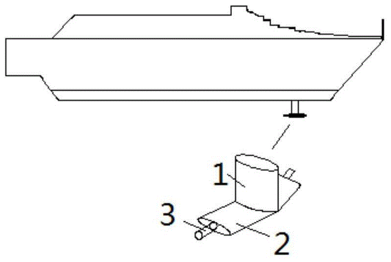
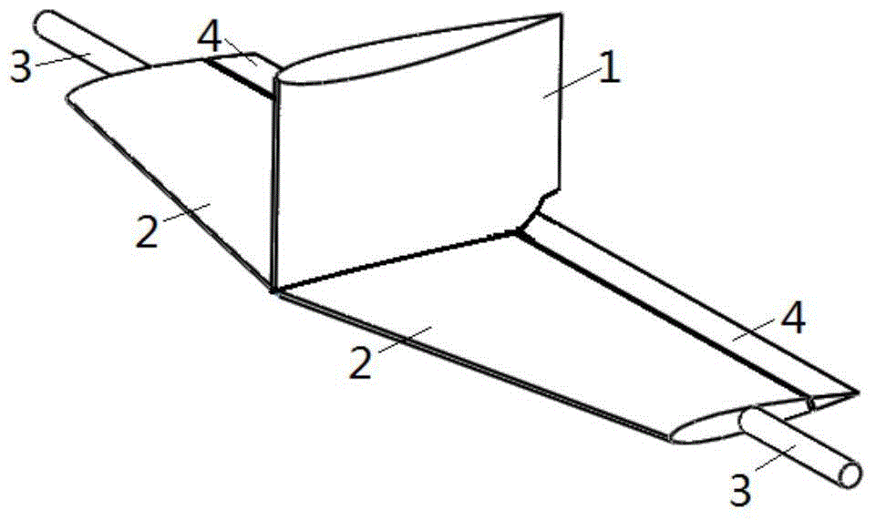
  • Stabilizing apparatus combined by T-shaped hydrofoil and rotor foils
  • Stabilizing apparatus combined by T-shaped hydrofoil and rotor foils

Examples


Embodiment Construction

[0022] The present invention will be further described below in conjunction with the accompanying drawings.

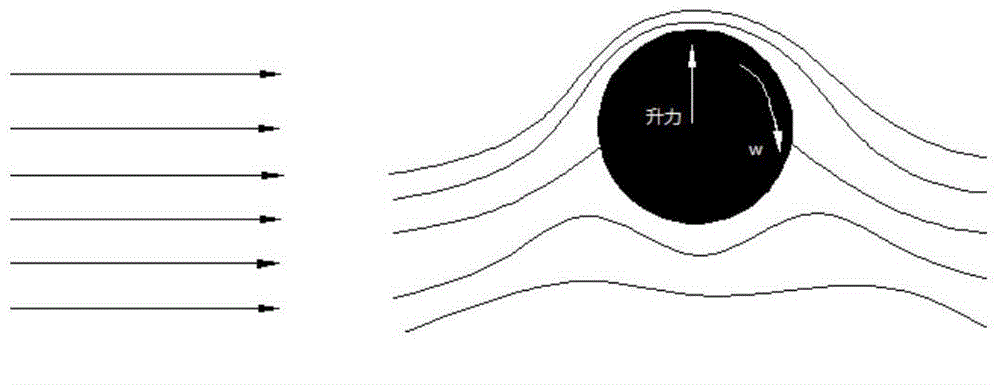
[0023] The present invention is by comprising strut, horizontal main wing, flap and retractable rotor wing as aileron. The rotor wings are driven by electric motors. The rotor wings retract into the aileron compartments in the horizontal main wing at high speeds, reducing drag, lowering fuel consumption and increasing speed. At low speed, the rotor wing is pushed out from the aileron compartment, and the rotor wing rotates around its own axis to generate lift, so that the ship can also play a good anti-rolling effect when the ship is at low or zero speed, improving the stability of the ship. Excellent seakeeping performance improves the riding environment and working environment for passengers and staff.

[0024] The upper end of the pillar is fixed on the bottom of the ship, the lower end is connected with the horizontal main wing, and the flap is connected with the...


PUM


Abstract

The invention belongs to the field of retractable and foldable hydrofoils of ships, and specifically relates to a stabilizing apparatus combined by a T-shaped hydrofoil and rotor foils. The stabilizing apparatus is designed to solve the problem of stabilization of high-speed ships at a low speed or at the zero speed, and the see-keeping and seaworthiness of the high-speed ships at the low speed are improved. The stabilizing apparatus is formed by a pillar, horizontal main foils, flaps, and the rotor foils, the upper end of the pillar 1 is fixed at the bottom of a ship, the lower end of the pillar 1 is vertically connected to the horizontal main foils 2, and the rotor foils 3 are cylindrical structures positioned in auxiliary foil cabins at the inner parts of the horizontal main foils and are driven by a hydraulic cylinder and a motor. When the high-speed ship is in the low speed, the conventional stabilization device can hardly produce a stabilization effect, and the sea-keeping of a hull is also affected by the shaking movement at the low speed and the zero speed. According to the stabilization apparatus, the problem of sea-keeping of the high-speed ships at the low speed is improved, the discomfort of passengers is reduced, the working environment of working personnel is improved, and the service quality of the working personnel is improved.

Description

technical field [0001] The invention belongs to the field of ship retractable and folding hydrofoils, and specifically relates to a design aimed at the problem of anti-rolling of high-speed ships at low or zero speeds, which improves the seakeeping and seaworthiness of high-speed ships at low speeds The T-shaped hydrofoil and rotor wing compound anti-rolling device. Background technique [0002] In recent years, the mode of maritime transportation has been developing towards diversification. With the advantages of large-scale and high-speed maritime transportation and lower freight compared with other transportation methods, more and more people choose ships as a means of transportation or travel. The wave piercing boat is a new type of high-speed boat. Its biggest feature is that it can adapt to harsh sea conditions and ensure high-speed operation. However, when the speed of the wave piercing craft is very small, the lift provided by the T-shaped hydrofoil will be very sm...

Claims


Application Information

Patent Timeline
Patent Type & Authority Applications(China)
IPC IPC(8): B63B39/06
Inventor 梁利华油兴田张松涛史洪宇张永庆苑佳
Owner HARBIN ENG UNIV
Learn More