Eureka AIR delivers breakthrough ideas for toughest innovation challenges, trusted by R&D personnel around the world.

Sheet-shaped punched part

A stamping and sheet-like technology, applied in the direction of supporting machines, mechanical equipment, machines/stands, etc., can solve problems such as affecting the quick fixation of the LCD screen, bumping the installer, easy to shake, etc., achieving good application prospects and easy implementation. , functional and practical effect

Inactive Publication Date: 2015-09-09
WUXI ZHONGYANG METAL PROD
View PDF4 Cites 1 Cited by
  • Summary
  • Abstract
  • Description
  • Claims
  • Application Information

AI Technical Summary

Problems solved by technology

[0002] In recent years, with the rapid development of the economy and the continuous improvement of people's living standards, a large number of electrical appliances have entered people's families. The existing sheet-shaped stamping parts used for fixing LCD screens are flat structures, and the sheet-like stamping parts are inserted into the LCD screen for fixing. When the base is fixed, it is not firmly fixed and is easy to shake, and the corners of the sheet stamping parts are at right angles. When the correspondence with the fixed base of the LCD screen is not accurate when plugged in, it is easy to scratch the fixed base of the LCD screen or hurt the installer. Affects the fast fixing of the LCD screen
[0003] CN 202691489 U file, although it can be fixed, has some disadvantages. First, this fixed plug-in fixing method is outdated and does not meet the trend of the existing market. Second, there is only one fixing hole, so the fixing is not firm enough, and the LCD screen is easy to tilt left and right , the third LCD back cover is not flat, there will be some protrusions at the bottom, and the size of the protrusions is different for different types of LCD screens
This invention can not fix the LCD screen, there are defects

Method used


Image

  • Sheet-shaped punched part

Examples


Embodiment Construction

[0013] The following will clearly and completely describe the technical solutions in the embodiments of the present invention with reference to the accompanying drawings in the embodiments of the present invention. Obviously, the described embodiments are only some, not all, embodiments of the present invention. Based on the embodiments of the present invention, all other embodiments obtained by persons of ordinary skill in the art without making creative efforts belong to the protection scope of the present invention.

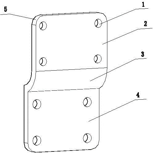
[0014] see figure 1 , the present invention provides a technical solution: a sheet-shaped stamping part, including an upper stamping body 2, a locking angle 3 and a lower stamping body 4, the connection between the upper stamping body 2 and the lower stamping body 4 is provided There are locking angles 3, rounded corners 5 are provided on both sides of the top of the upper sheet stamping body 2, a plurality of fixing holes 1 are provided at the four corners of...


PUM


Abstract

The invention discloses a sheet-shaped punched part. The sheet-shaped punched part comprises an upper punched body, a position clamping corner and a lower punched body. The position clamping corner is arranged at the position of connection between the upper punched body and the lower punched body. Circular corners are arranged on the two sides of the top of the upper punched body respectively, a plurality of fixing holes are formed in the four corners of the upper punched body, circular corners are arranged on the two sides of the bottom of the lower punched body, and a plurality of fixing holes are formed in the four corners of the lower punched body. The sheet-shaped punched part is simple in structure, practical in function and low in cost. Due to the fact that the position clamping corner is arranged, the sheet-shaped punched part can be clamped on a rear cover of a liquid crystal display screen, and the liquid crystal display screen can be firmly fixed. Due to the fact that the corners of the sheet-shaped punched part are designed to be circular corners, the sheet-shaped punched part is attractive in appearance and stable in structure, and easy to implement, meets an existing trend of the market, and has the good application prospect.

Description

technical field [0001] The invention relates to the field of mechanical parts manufacturing, in particular to a sheet stamping part. Background technique [0002] In recent years, with the rapid development of the economy and the continuous improvement of people's living standards, a large number of electrical appliances have entered people's families. The existing sheet-shaped stamping parts used for fixing LCD screens are flat structures, and the sheet-like stamping parts are inserted into the LCD screen for fixing. When the base is fixed, it is not firmly fixed and is easy to shake, and the corners of the sheet stamping parts are at right angles. When the correspondence with the fixed base of the LCD screen is not accurate when plugged in, it is easy to scratch the fixed base of the LCD screen or hurt the installer. Affects the fast fixing of the LCD screen. [0003] CN 202691489 U file, although it can be fixed, has some disadvantages. First, this fixed plug-in fixing m...

Claims


Application Information

Patent Timeline
Patent Type & Authority Applications(China)
IPC IPC(8): F16M11/16F16M11/04
Inventor 孙志刚
Owner WUXI ZHONGYANG METAL PROD
Why Eureka
Eureka Blog
Learn More