Speed measurement device for crusher rotor

A speed measuring device and crusher technology, which is applied to devices using optical methods, grain processing, etc., can solve the problems of large vibration amplitude, affecting the service life of the speed measuring device, and large ash, so as to achieve the effect of guaranteed service life

Inactive Publication Date: 2015-09-16
ZUNYI LIXIN MACHINERY
6 Cites 0 Cited by

AI-Extracted Technical Summary

Problems solved by technology

[0002] In the prior art, the speed measurement of the rotor of the crusher is generally carried out by installing a conventional speed measurement device. However, the speed measurement of the crusher rotor is special in that the vibration amplitude is relatively ...

Method used

[0018] Thus, by the discontinuous reflection of the mirror 22 to infrared rays during the rotation of ...

Abstract

The invention provides a speed measurement device for a crusher rotor. The speed measurement device comprises a rotor center shaft, a rotor, a shell, infrared devices and a reflective mirror, wherein the rotor is fixed onto the rotor center shaft, the reflective mirror is fixed onto the side of the rotor, the infrared devices are fixed onto one surface, which corresponds to the rotor center shaft and the rotor, of the shell and comprise an infrared emission device and an infrared receiving device which are both just opposite to the reflective mirror, and infrared light emitted from the infrared emission device is reflected by the reflective mirror and then can be received by the infrared receiving device. With the infrared devices, the speed measurement effect cannot be affected by large-amplitude vibration of a crusher during working; with an ash removal element, the speed measurement effect cannot by affected by much ash, and the service life of the speed measurement device can be guaranteed.

Application Domain

Devices using optical meansGrain treatments

Technology Topic

Speed measurementOptoelectronics +1

Image

  • Speed measurement device for crusher rotor
  • Speed measurement device for crusher rotor
  • Speed measurement device for crusher rotor

Examples

  • Experimental program(1)

Example Embodiment

[0016] The technical solution of the present invention is further described below, but the scope of protection is not limited to the description.
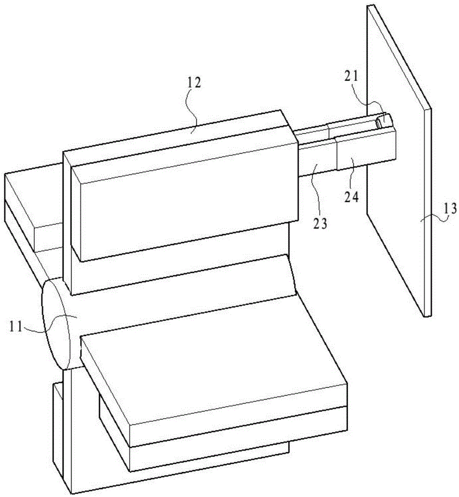
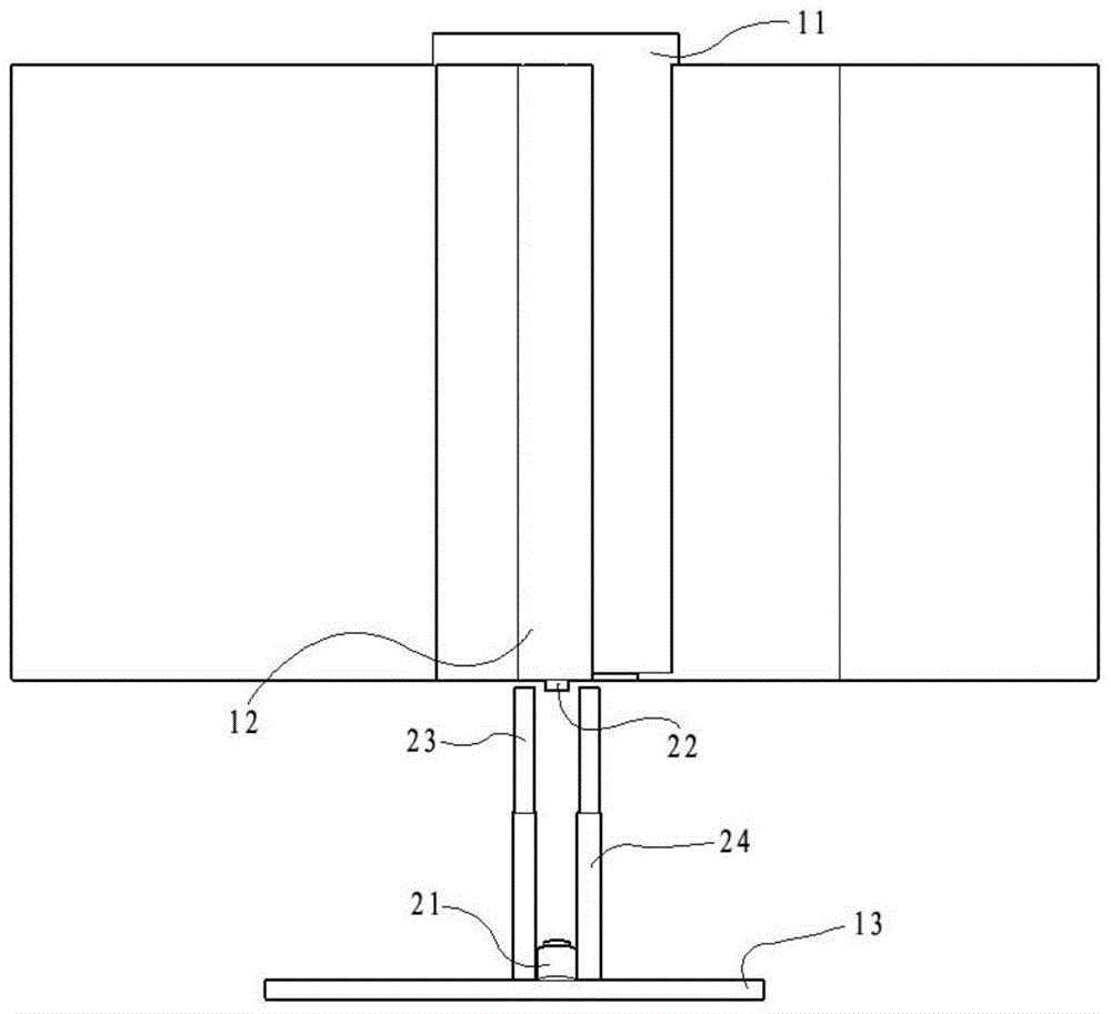
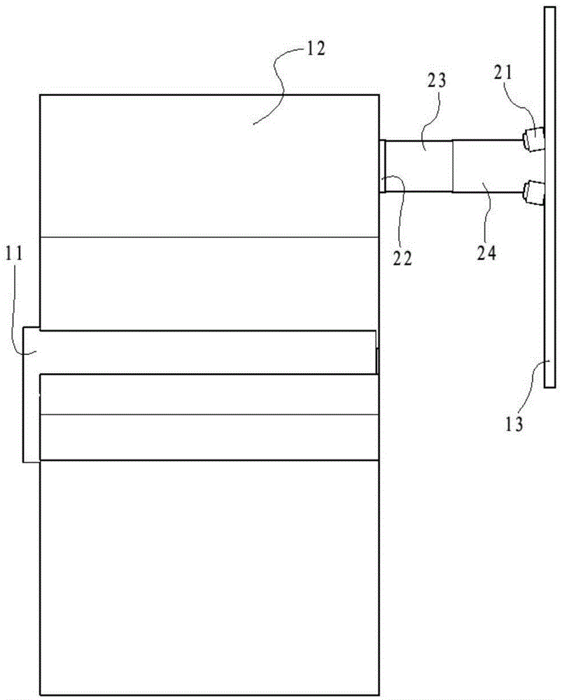
[0017] like Figure 1 to Figure 3 The crusher rotor speed measuring device shown includes a rotor shaft 11, a rotor 12, a housing 13, an infrared device 21, and a mirror 22; the rotor 12 is fixed on the rotor shaft 11, and the side of the rotor 12 is fixed with a reflective A mirror 22, an infrared device 21 is fixed on the side of the housing 13 corresponding to the rotor axis 11 and the rotor 12; the infrared device 21 is an infrared emitting device and an infrared receiving device, and both the infrared emitting device and the infrared receiving device are facing the reflection mirror 22, and the infrared light emitted by the infrared emitting device is reflected by the reflective mirror 22 and can be received by the infrared receiving device.
[0018] Thus, the rotational speed of the rotor 12 can be easily calculated through the intermittent reflection of the infrared rays by the reflective mirror 22 during the rotation of the rotor 12 in combination with the time.
[0019] Further, in order to ensure better signal transmission and reception effects, the light reflection angle should not be too large, so in the infrared device 21, the angle between the orientation of the infrared emitting device and the orientation of the infrared receiving device is less than 15°.
[0020] In order to ensure a continuous good speed measurement effect and avoid signal reception failure caused by the large ash blocking the reflector 22, the ash removal part 23 is also included. The ash removal part 23 is fixed on the housing 13 and is located on the side of the infrared device 21.
[0021] Specifically, the position of the ash removing member 23 is on the arc corresponding to the arc formed by the mirror 22 as the rotor 12 rotates.
[0022] Further, in order to save costs, the ash removal member 23 is fixed by the fixing member 24, and the ash removal member 23 and the reflector 22 partially overlap in side projection.
[0023] As the most preferred solution, the ash removal member 23 is a brush or a sponge.

PUM

no PUM

Description & Claims & Application Information

We can also present the details of the Description, Claims and Application information to help users get a comprehensive understanding of the technical details of the patent, such as background art, summary of invention, brief description of drawings, description of embodiments, and other original content. On the other hand, users can also determine the specific scope of protection of the technology through the list of claims; as well as understand the changes in the life cycle of the technology with the presentation of the patent timeline. Login to view more.

Similar technology patents

Rotary screw air compressor with long service life

InactiveCN109209889Aspeed up heat dissipationGuaranteed service life
Owner:浙江荣鑫纤维股份有限公司

Lampblack gas filtering treatment method

InactiveCN112316649AGuaranteed purification effectGuaranteed service life
Owner:武金海

Anti-static misfire ground and manufacturing method thereof

PendingCN106930503AGuaranteed service life
Owner:杭州电盾装饰材料有限公司

Classification and recommendation of technical efficacy words

  • Guaranteed service life

Soybean milk making method of soybean milk machine

ActiveCN105411430Ashorten pulping cycleGuaranteed service life
Owner:HONGYANG HOME APPLIANCES

Temperature regulator

ActiveCN104344063AGuaranteed service life
Owner:ZHEJIANG SANHUA AUTOMOTIVE COMPONENTS

Disposal method and disposal device for greasy blockage of air conditioner system and air conditioner

InactiveCN105465970AAvoid Capability DecayGuaranteed service life
Owner:GD MIDEA AIR-CONDITIONING EQUIP CO LTD +1
Why Eureka
Try Eureka