A fuel tank mold

A fuel tank mold and mold body technology, which is applied in the field of fuel tank molds, can solve the problems of deformation connection strength and air tightness, easy deformation of the fuel tank body shape, and increased cost of finished products, so as to improve the yield of finished products, prevent large-scale deviation, and use The effect of material saving

Active Publication Date: 2017-05-10
NINGBO FANGZHENG TOOL
View PDF2 Cites 0 Cited by
  • Summary
  • Abstract
  • Description
  • Claims
  • Application Information

AI Technical Summary

Problems solved by technology

[0002] At present, in order to avoid various auxiliary mechanisms and blanking mechanisms at the upper end of the mold, the fuel tank mold sets the blowing needle mechanism on the mold body corresponding to the lower part of the mold cavity, and the position of the blowing needle corresponding to the mold cavity is the position of the fuel tank after molding. Therefore, the relatively small end of the fuel tank body is located at the bottom, while the relatively large end of the tank body is located at the top; It is easy to go down, so that the wall thickness of the lower part of the fuel tank body is relatively thick, and the raw materials are relatively required, which increases the cost of the fuel tank; and the uneven wall thickness will make the fuel tank in water-cooled shape after forming. Uneven shrinkage, the shape of the fuel tank body is easy to deform, and the fuel tank body is also easy to deviate in a large range, resulting in deformation of the fuel tank body at the clamping position, resulting in a low rate of finished products, which eventually leads to a substantial increase in the cost of the finished product. The slight deformation of the fuel tank body at the clamping position will easily lead to leakage during actual use, and the quality stability is poor; moreover, the inserts near the fuel tank opening are all drilled after the fuel tank is formed, and then welded If it goes up, it is easy to cause the deformation of the tank wall near the insert, which makes the connection strength and air tightness worse, and it is easy to leak during actual use, and the quality stability is poor

Method used


Image

  • A fuel tank mold
  • A fuel tank mold
  • A fuel tank mold

Examples


Embodiment Construction

[0018] The present invention will be further described below in conjunction with the accompanying drawings and specific embodiments.

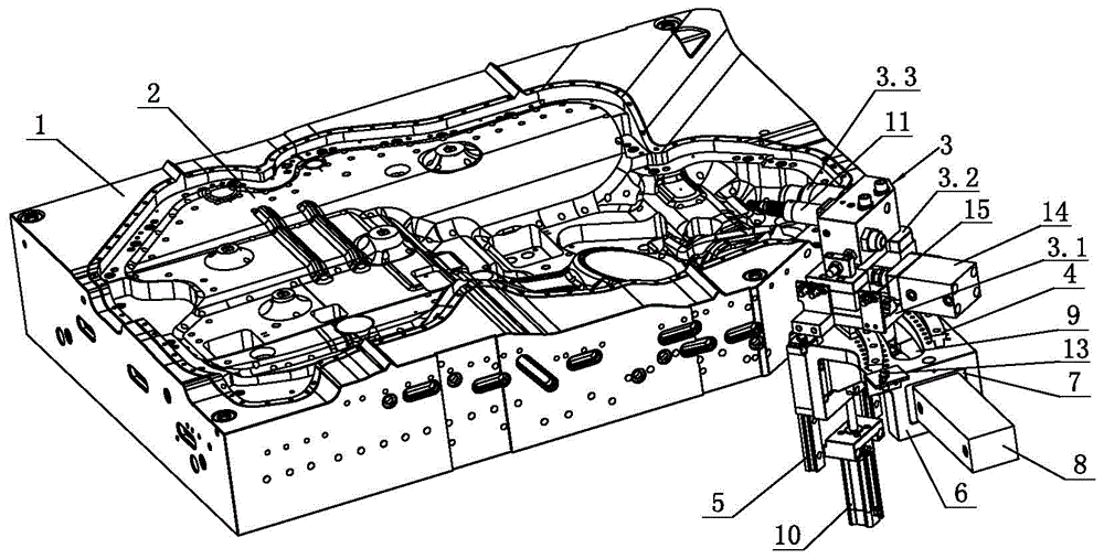
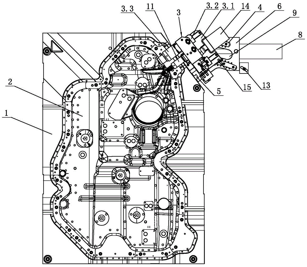
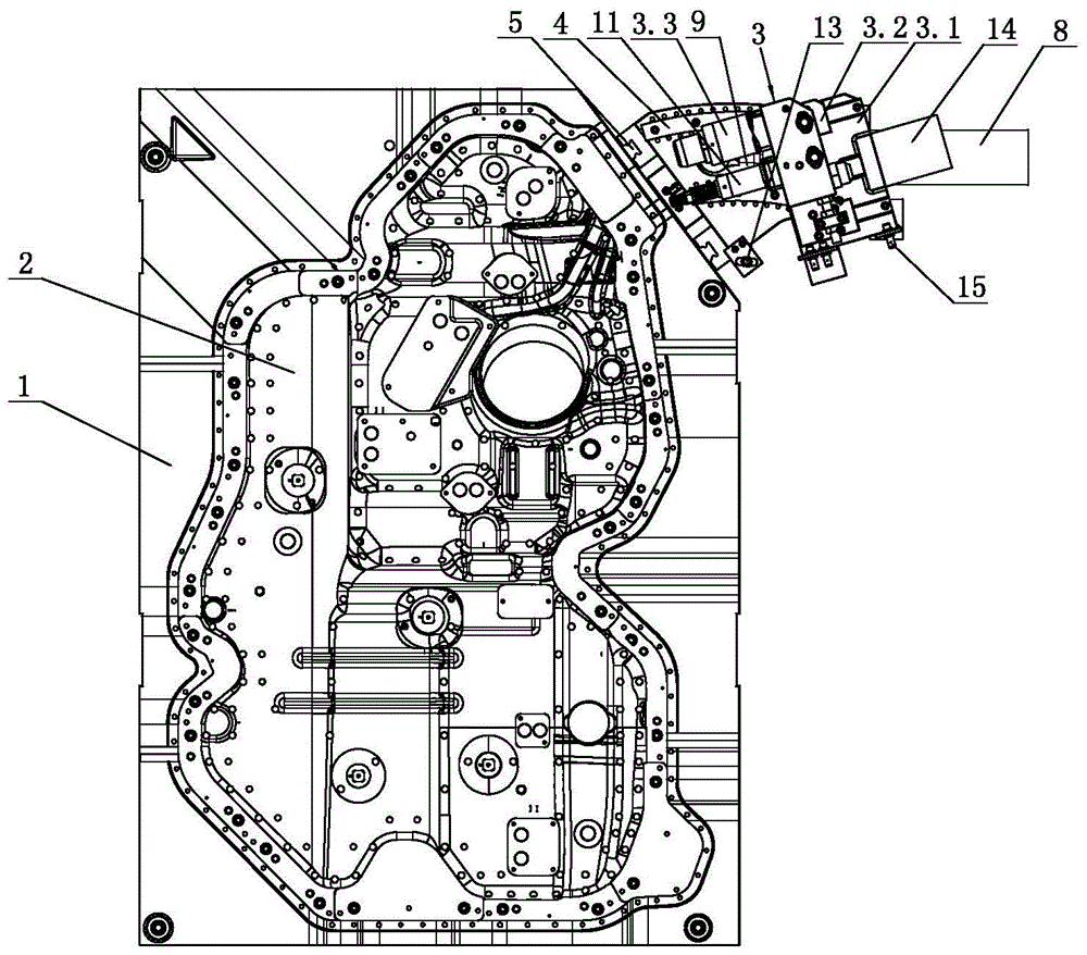
[0019] Such as figure 1 , figure 2 , image 3 , Figure 4 with Figure 5 Shown, a kind of fuel tank mould, it comprises the mold body 1 on the mold base (the mold base is not shown in the accompanying drawing) and the mold cavity 2 on the mold body 1 (of course also includes other components, but because it does not involve this Invention point of the invention, so it will not be repeated here), the mold body 1 is provided with a needle blowing mechanism 3, and the needle blowing mechanism 3 is located at the upper end of the mold body 1, and the upper end of the mold cavity 2 The maximum width is smaller than the maximum width of the lower end of the cavity 2, that is, the relatively small end of the fuel tank body is located at the top, while the relatively large end of the fuel tank body is located at the bottom, and the upper end of th...


PUM


Abstract

An oil tank mould comprises a mould body (1) on a mould base and a cavity (2) in the mould body (1). A needle blowing mechanism (3) is located at the upper end of the mould body (1), the width of the upper end of the cavity (2) is smaller than that of the lower end of the cavity (2), the upper end of the mould body (1) is provided with an arc-shaped rail (4) and a linear rail (5), and the arc-shaped rail (4) is connected with the linear rail (5) through an L-shaped support (6); the support (6) is provided with an arc-shaped through hole (9) which extends along the arc-shaped rail (4), and the needle blowing mechanism (3) is hinged to a piston rod of a first air cylinder (8) and provided with an insert fixture (11). Compared with the prior art, the oil tank mould has the advantages that used materials are saved, water-cooling sizing of products is facilitated, the product cost can be significantly lowered, and the quality stability is better.

Description

technical field [0001] The invention relates to an oil tank mold. Background technique [0002] At present, in order to avoid various auxiliary mechanisms and blanking mechanisms at the upper end of the mold, the fuel tank mold sets the blowing needle mechanism on the mold body corresponding to the lower part of the mold cavity, and the position of the blowing needle corresponding to the mold cavity is the position of the fuel tank after molding. Therefore, the relatively small end of the fuel tank body is located at the bottom, while the relatively large end of the tank body is located at the top; It is easy to go down, so that the wall thickness of the lower part of the fuel tank body is relatively thick, and the raw materials are relatively required, which increases the cost of the fuel tank; and the uneven wall thickness will make the fuel tank in water-cooled shape after forming. Uneven shrinkage, the shape of the fuel tank body is easy to deform, and the fuel tank bod...

Claims


Application Information

Patent Timeline
Patent Type & Authority Patents(China)
IPC IPC(8): B29C49/48B29C49/60
Inventor 王锦浪程苗张修恩葛小翔陈聪
Owner NINGBO FANGZHENG TOOL
Why Eureka
Try Eureka