Automatic lifting device and method for tower-shaped mast
An automatic lifting and mast technology, applied in the directions of masts, transportation and packaging, ship parts, etc., can solve problems such as major property, collision and loss of mast lifting devices, and achieve the effect of solving the laborious and lightweight artificial lifting of the mast.
- Summary
- Abstract
- Description
- Claims
- Application Information
AI Technical Summary
Problems solved by technology
Method used
Image
Examples
Embodiment 1
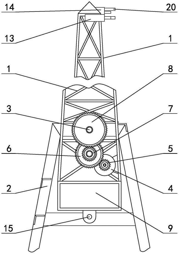
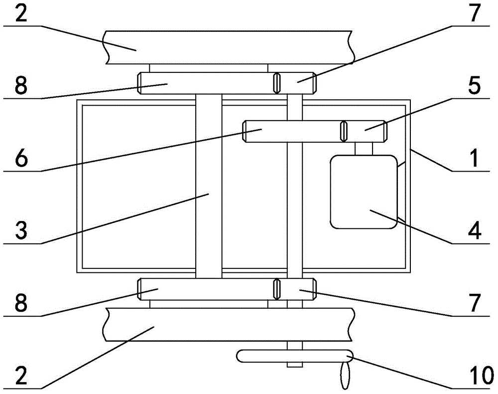
[0033] in such as figure 1 image 3In the shown embodiment 1, a tower mast automatic lifting device, the tower mast 1 is rotatably arranged on the mast base frame 2 of the ship, the mast base frame is a U-shaped structure with the opening facing upward, the base A horizontal shaft 3 perpendicular to the direction of navigation of the ship is provided on the frame, and the lower part of the mast is hinged to the horizontal shaft. meshing, a reduction gear 7 is provided on the wheel shaft of the intermediate gear, a fixed gear 8 coaxial with the horizontal axis is provided on the mast base frame, the reduction gear meshes with the fixed gear, and a counterweight is provided at the end of the mast below the horizontal axis 9. There is also a hand wheel 10 on the wheel shaft of the intermediate gear. When the mast motor rotates, the driving gear drives the reduction gear to rotate through the intermediate gear, and the mast rotates relative to the horizontal axis and the fixed ge...
Embodiment 2
[0042] The swing mechanism of embodiment 2 (see Figure 4 ) includes a swing motor (not shown in the figure), the swing motor is a speed-regulating motor, the power shaft 21 of the swing motor is stacked with a forward drive gear 22 and a reverse drive gear 23, the forward drive gear and the reverse drive gear The drive gears are all sector gears with the same number of teeth and are arranged in a misplaced position. The swing mechanism also includes a swing gear 24, the forward drive gear is intermittently meshed with the swing gear, the reverse drive gear is intermittently meshed with the reversing gear 25, and the reversing gear is in contact with the reversing gear. The swing gear meshes, and the swing gear meshes with the swing output gear 27 through a reduction transmission gear 26. When the forward drive gear meshes with the swing gear, the reverse drive gear disengages with the reversing gear, and when the reverse drive gear meshes with the reversing gear , the forward...
Embodiment 3
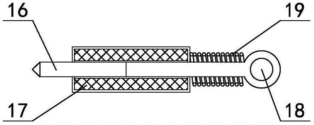
[0045] The mast top of embodiment 3 is provided with emergency anti-collision mechanism (see Figure 5 ), the emergency anti-collision mechanism includes a straight rod 28 and a compression spring 29, the length direction of the straight rod is parallel to the length direction of the ship, the straight rod is slidably worn on the mast, and the front end of the straight rod is provided with a bumper , the compression spring is sleeved on the straight rod, one end of the compression spring is in contact with the impact head, the other end is in contact with the mast, the rear end of the straight rod is provided with a limit plate 31 to prevent the straight rod from coming out, the limit plate The end of the straight rod on the rear side is fixed with a stay cord 32, and the stay cord is connected with the draw ring through a pulley mechanism 33. The obstacle detection device of this embodiment is arranged below the straight rod; a clutch is provided between the driving gear and ...
PUM
 Abstract
Description
Claims
Application Information
 - R&D
- Intellectual Property
- Life Sciences
- Materials
- Tech Scout
- Unparalleled Data Quality
- Higher Quality Content
- 60% Fewer Hallucinations
Browse by: Latest US Patents, China's latest patents, Technical Efficacy Thesaurus, Application Domain, Technology Topic, Popular Technical Reports.
© 2025 PatSnap. All rights reserved.Legal|Privacy policy|Modern Slavery Act Transparency Statement|Sitemap|About US| Contact US: help@patsnap.com


