Straight rack type wind turbine blade adjusting mechanism

A technology of adjusting mechanism and wind rotor blades, which is applied to wind turbines, wind turbines, wind turbine control and other directions that are consistent with the wind direction, can solve the problems of unsatisfactory blade angle control, poor synchronization, and unsatisfactory power generation costs, and achieves It is convenient for daily maintenance, large transmission ratio, and the effect of improving the efficiency of wind energy utilization

Inactive Publication Date: 2015-09-23
张效新 +1
View PDF7 Cites 5 Cited by
  • Summary
  • Abstract
  • Description
  • Claims
  • Application Information

AI Technical Summary

Problems solved by technology

The blade angle is independently adjusted and the synchronization is poor
[0004] In addition, the gear structure of a single-frame impeller disclosed in the invention patent and utility model patent ZL 201420608931.5 of the invention patent application number 201410561011.7 is not ideal in terms of blade angle control
As a result, the overall operation and unit power generation cost are still unsatisfactory

Method used


Image

  • Straight rack type wind turbine blade adjusting mechanism
  • Straight rack type wind turbine blade adjusting mechanism
  • Straight rack type wind turbine blade adjusting mechanism

Examples


Embodiment

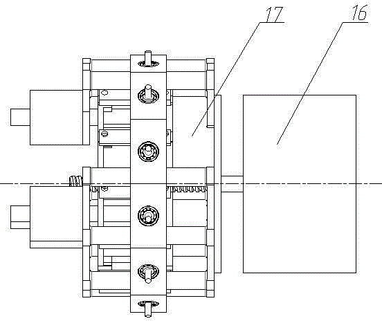
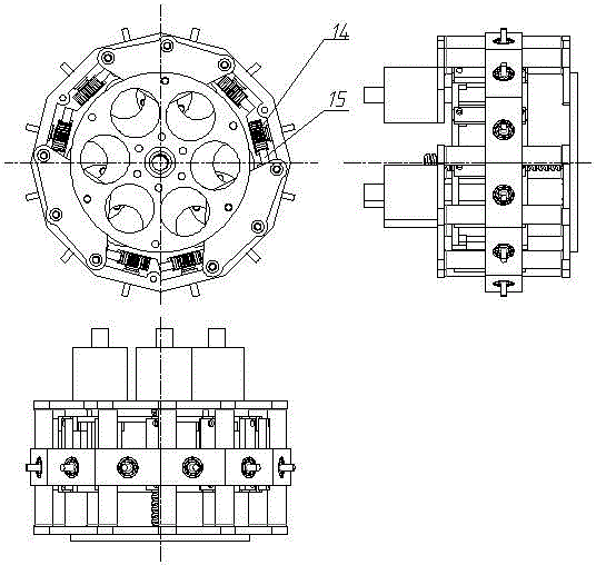
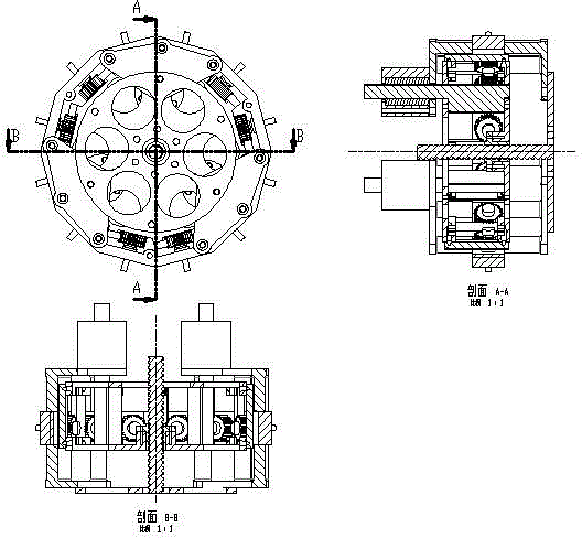
[0018] Depend on Figure 1 to Figure 5 It can be seen that the technical solution of the present invention includes the power unit 16 with the main shaft horizontally arranged, the drive motor fixed plate 2, the cabin cylinder wall 6, the front plate 4 fixed by the rack, the rear plate 12 fixed by the rack, the front pressure plate 1, and the rear platen 8. Gear 14, rack 15, lead screw 3, nut 5, slide bar bearing seat 9, slide bar bearing 10, slide bar 11, blade shaft 7, bearing 13; power unit 16 is placed in the driving motor of the whole adjustment mechanism 17 One side of the fixed disk;

[0019] The overall adjustment mechanism 17 is a rack and pinion adjustment mechanism; the power unit 16 for adjusting and controlling the blade angle in this embodiment adopts an electric motor; the cabin cylinder wall 6 of the overall adjustment mechanism 17 is a regular dodecagonal tube, and the front pressure plate 1 On the drive motor fixed plate 2, the cabin cylinder wall 6 is insta...


PUM


Abstract

The invention relates to the technical field of wind power generation equipment, in particular to a straight rack type wind turbine blade adjusting mechanism to solve the problems that the adjusting mechanism in the existing gear wheel technology is poor in reliability, a large torque of the adjusting mechanism is required, and a blade angle is difficult to control. The straight rack type wind turbine blade adjusting mechanism comprises a driving motor fixed disk, an engine room cylindrical wall, a rack fixed front disk, a rack fixed rear disk, a front pressure disk, a rear pressure disk, a gear and rack mechanism, a screw and nut mechanism, three sliding bar bearing pedestals, sliding bar bearings and sliding bars; the front pressure disk is connected on the driving motor fixed disk; the three sliding bar bearing pedestals are uniformly arranged on the rear pressure disk; blade shafts are mounted on the engine room cylindrical wall by bearings; gears are fixed at the end parts of the blade shafts on the inner side of the engine room cylindrical wall and engaged with racks; a nut is fixed in the middle of the rack fixed front disk; and a screw is matched with the nut and connected with an output mechanism of a power unit. According to the straight rack type wind turbine blade adjusting mechanism, by changing the structure of the blade adjusting mechanism and a transmission mode, the transmission stability and the accuracy are improved.

Description

technical field [0001] The invention relates to the technical field of wind power generation equipment, in particular to a straight rack type wind rotor blade adjustment mechanism. Background technique [0002] The wind turbine blade adjustment mechanism is connected with the power unit to drive the main transmission part to move, and the windward angle of the blade is adjusted through the transmission of the transmission mechanism. [0003] At present, some wind turbine blades are installed at a fixed angle, and some are independently adjusted for the blade angle. The independent adjustment of blade angle is poor in synchronization. [0004] In addition, the gear structure of a single-frame impeller disclosed in the invention patent application number 201410561011.7 and the utility model patent ZL 201420608931.5 is not ideal in terms of blade angle control. As a result, the overall operation and unit power generation cost are still unsatisfactory. Contents of the invent...

Claims


Application Information

Patent Timeline
Patent Type & Authority Applications(China)
IPC IPC(8): F03D1/06F03D7/04
CPCF03D1/06F03D7/04Y02E10/72
Inventor 张导宇郭佳伟赵海平白俊平张秀国贾雪姣刘宁杨飞韩艳洁张效新白振义许建伟
Owner 张效新
Why Eureka
Try Eureka